
Printing systems

a printing system and printing technology, applied in the field of printing systems, can solve the problems of low printing efficiency, low printing efficiency, and low printing efficiency, and achieve the effect of maximizing continuous printing run time and minimizing printer downtim

Inactive Publication Date: 2006-11-30
XEROX CORP
View PDF65 Cites 21 Cited by
  • Summary
  • Abstract
  • Description
  • Claims
  • Application Information

AI Technical Summary

Benefits of technology

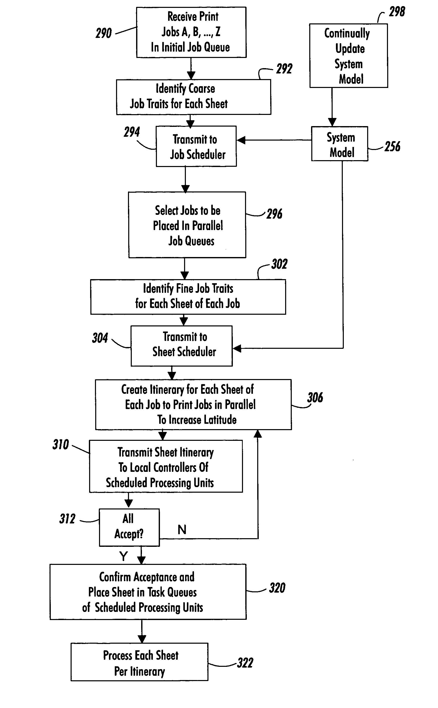
[0023] In accordance with one aspect, a method is disclosed. Print jobs each including a plurality of sheets to be processed are received. Current operational capabilities of at least one processing unit of a document processing system are determined, which processing unit has a predetermined nominal operational latitude. A sequence of interleaved sheet processing of the sheets of each print job is scheduled based at least on determination of the operational capabilities of the processing unit. Short term average departures from the nominal operational latitude of the processing unit are reduced. An operational latitude of the document processing system is increased.

Problems solved by technology

As is known by product developers and operators of such systems, certain classes of jobs stress the print engine and lead to poor performance or failures.
Printing an extended job with particularly high or low area coverage can create wear or charging distribution problems in the developer sump, subsequently leading to problems such as high background, bead carry out, drift in developed mass per area, and so on.
Stress jobs are often said to be outside of the operational latitude of the system which leads to a reduced performance of the print engines.
While countermeasures are generally known for recovering from the performance shortfalls or failures associated with the operation outside of the print system's latitude, there is usually collateral waste or loss in productivity.
However, this approach may be costly or even non-viable to develop, and may decrease productivity or increase waste when implemented.
If too low of an average consumption rate for any toner persists for too many pages, the marking materials are not used at a sufficient rate, and the supply is not regularly replenished with the fresh material.
Over an extended period, the marking material stored in the developer housing becomes damaged due to the constant churning of the material under high shear.
Examples of damage are the impaction of toner particles onto carrier beads, the impaction of additives onto toner, and the degradation of carrier bead coatings.
Surface charge distribution of materials damaged in the developer housing can become skewed or pathologically abnormal.
Images printed with the damaged material will have one or more image defects, such as color imbalances, fine line growth or shrinkage, or high levels of background toner in the nominally white region of a page, which can appears as a color shift or dirt over the entire printable area of the page.
A wasteful countermeasure to printing low area coverage jobs is to purge significant quantities of damaged toner from the developer sump.

Method used


Image

  • Printing systems
  • Printing systems
  • Printing systems

Examples


Embodiment Construction

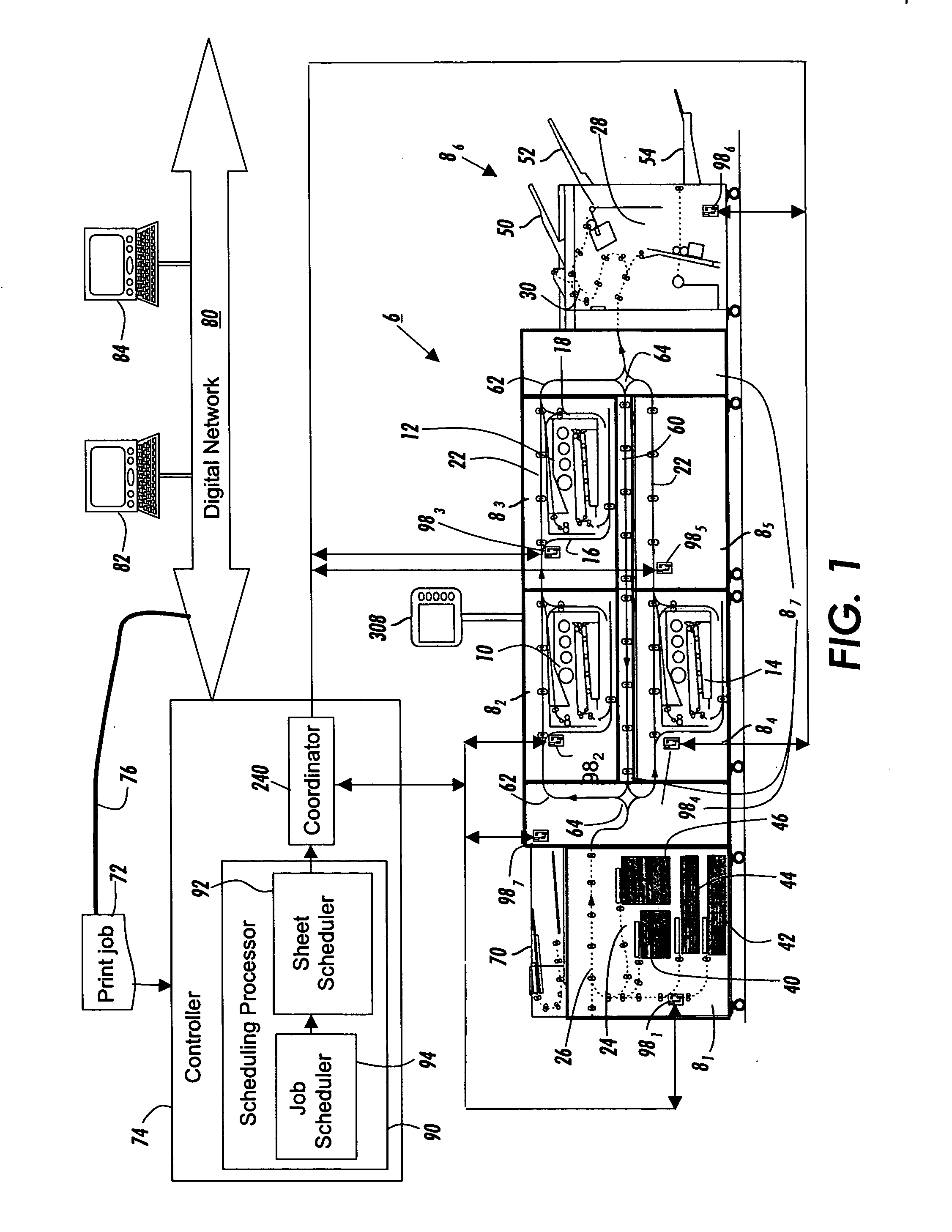
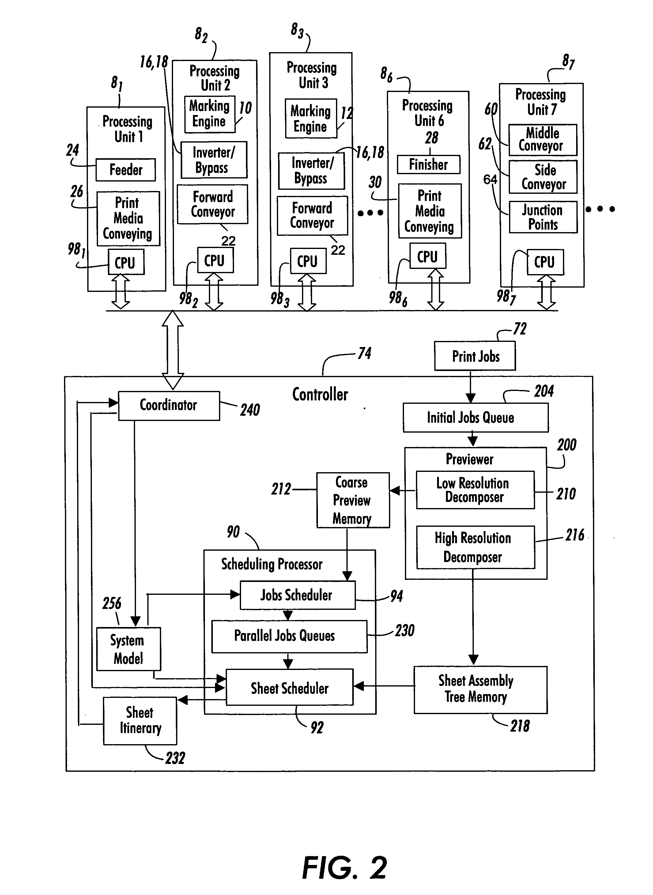
[0029] With reference to FIG. 1, an example printing or document processing system 6 is a modular printing system including first, second, . . . , nth processing units or elements 81, 82, 83, 84, 85, 86, . . . , 8n. In one embodiment, the first, second, third, fourth, fifth and sixth processing units 81, 82, 83, 84, 85, 86 are interconnected by a seventh or print media processing unit 87, i.e., sheet conveyance processing unit. The processing units 81, 82, 83, 84, 85, 86, 87, . . . , 8n cooperate to produce completely assembled print jobs at high rate. While seven processing units are illustrated, the plurality of processing units may include two, three, four, five, six, seven, eight, or more processing units.

[0030] For example, in the printing system 6, the second, third and fourth processing units 82, 83, 84 include associated marking engines 10, 12, 14 and associated entry and exit inverter / bypasses 16, 18. In some embodiments, one or more operational components of the processin...


PUM


Abstract

In a document processing system, print jobs each including a plurality of sheets to be processed are received. Current operational capabilities of at least one processing unit of a document processing system are determined, which processing unit has a predetermined nominal operational latitude. A sequence of interleaved sheet processing of the sheets of each print job is scheduled based at least on determination of the operational capabilities of the processing unit. Short term average departures from the nominal operational latitude of the processing unit are reduced. An operational latitude of the document processing system is increased.

Description

CROSS REFERENCE TO RELATED APPLICATIONS [0001] The following applications, the disclosures of each being totally incorporated herein by reference are mentioned: The following copending applications, the disclosures of which are incorporated by reference in their entireties, are mentioned: [0002] U.S. patent application Ser. No. ______ (Attorney Docket No. 20050281-US-NP), filed contemporaneously herewith, entitled PRINTING SYSTEM, by Robert M. Lofthus, et al.; [0003] U.S. patent application Ser. No. ______ (Attorney Docket No. 20050382-US-NP), filed contemporaneously herewith, entitled SCHEDULING SYSTEM, by Robert M. Lofthus, et al. U.S. application Ser. No. 10 / 924,458 (Attorney Docket A3548-US-NP), filed Aug. 23, 2004, entitled “PRINT SEQUENCE SCHEDULING FOR RELIABILITY,” by Robert M. Lofthus, et al.; [0004] U.S. application Ser. No. 10 / 953,953 (Attorney Docket No. A3546-US-NP), filed Sep. 29, 2004, entitled “CUSTOMIZED SET POINT CONTROL FOR OUTPUT STABILITY IN A TIPP ARCHITECTURE...

Claims


Application Information

Patent Timeline
IPC IPC(8): G03G15/00
CPCG03G2215/00126G03G15/50
Inventor GERMAN, KRISTINE A.LOFTHUS, ROBERT M.
Owner XEROX CORP
Learn More