Intraocular lens injector

a technology of injectors and intraocular lenses, which is applied in the field of intraocular lens injectors, can solve problems such as eye astigmatism and eye burden

Inactive Publication Date: 2006-11-30
NIDEK CO LTD
View PDF9 Cites 20 Cited by
  • Summary
  • Abstract
  • Description
  • Claims
  • Application Information

AI Technical Summary

Problems solved by technology

If a large incision is made, it may become a burden on the eye and also cause astigmatism of the eye after the operation.

Method used


Image

  • Intraocular lens injector
  • Intraocular lens injector
  • Intraocular lens injector

Examples


Embodiment Construction

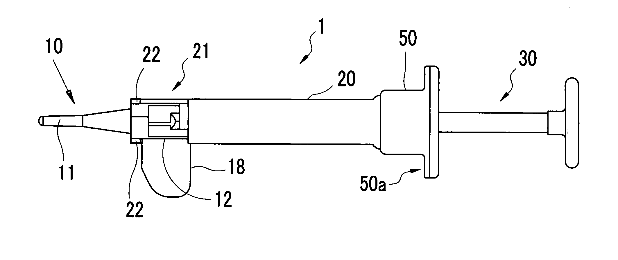
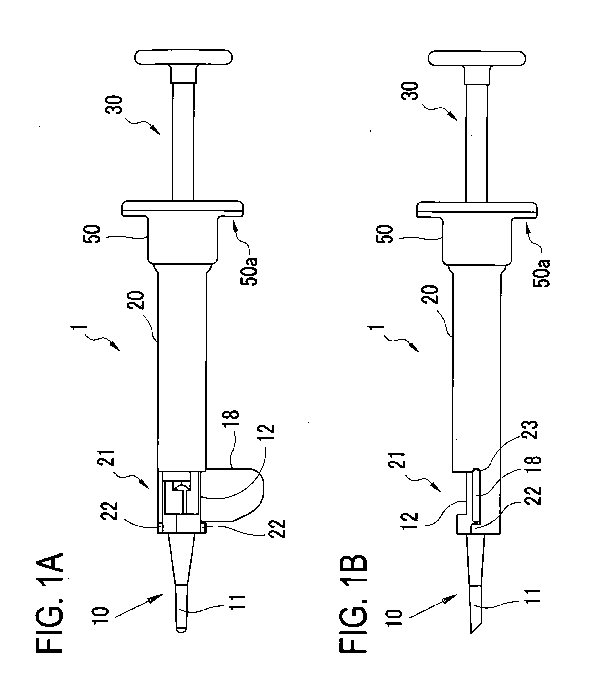
[0020] A detailed description of a preferred embodiment of the present invention will now be given referring to the accompanying drawings. FIGS. 1A and 1B are schematic structural views of an intraocular lens injector 1 in the present embodiment; FIG. 1A is a plan view and FIG. 1B is a side view.

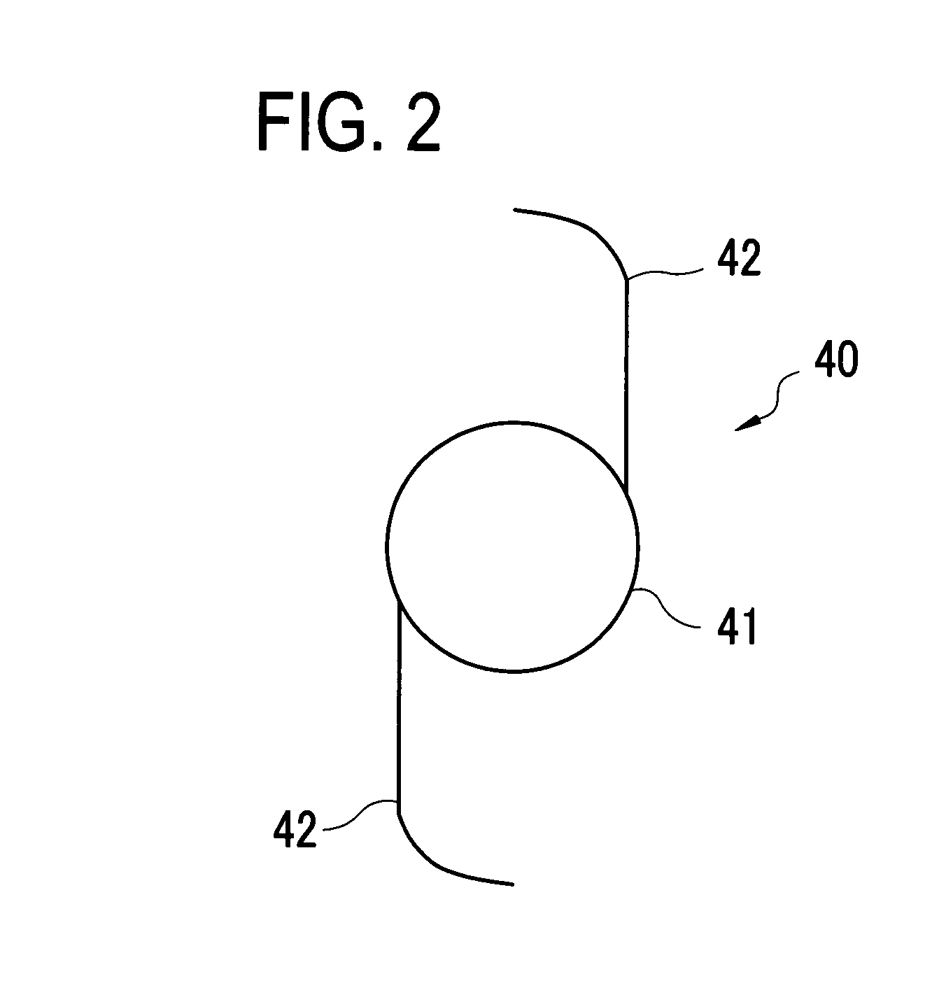
[0021] The injector 1 includes, in order of insertion into an eye, a substantially cylindrical lens holding unit (a lens cartridge) 10 provided with a substantially cylindrical (tubular) insertion part 11 which is insertable in an incision made in the eye and a setting part 12 in which an intraocular lens (hereinafter, IOL) 40 (see FIG. 2) is to be placed (set), a substantially cylindrical (tubular) main unit 20 in which the lens holding unit 10 is mounted, and a push unit 30 inserted in the main unit 20 and the lens holding unit 10. This push unit 30 is used to push out the IOL 40 placed in the setting part 12 of the lens holding unit 10 through a front end (a tip end) of the insertion par...


PUM


Abstract

An intraocular lens injector for injecting a foldable intraocular lens in an aye, comprises: a substantially cylindrical main unit including a substantially cylindrical insertion part which is insertable through an incision made in the eye, the main unit being adapted to internally hold the intraocular lens and release the intraocular lens to the outside of the injector through the insertion part; a push unit inserted in the main unit to push the intraocular lens to the outside through the insertion part, the push unit being disposed to be unrotatable relative to the main unit but movable in an axial direction of the main unit; and a rotatable member disposed to be rotatable relative to the main unit.

Description

BACKGROUND OF THE INVENTION [0001] 1. Field of the Invention [0002] The present invention relates to an intraocular lens injector for injecting an intraocular lens into an eye of a patient. [0003] 2. Description of Related Art [0004] As one of operative treatments for cataract, generally used is a method of removing a crystalline lens from an eye of a patient and then injecting an intraocular lens in place of the crystalline lens. To inject the intraocular lens, the following steps are performed: first making an incision in the eye; fragmenting and aspirating a clouded crystalline lens through the incision by for example an ultrasonic cataract-surgery device (a phaco-emulsification device); and then injecting the intraocular lens into the eye through the incision to implant it in place of the crystalline lens. [0005] If a large incision is made, it may become a burden on the eye and also cause astigmatism of the eye after the operation. To prevent such disadvantages, an intraocular ...

Claims


Application Information

Patent Timeline
Patent Type & Authority Applications(United States)
IPC IPC(8): A61F9/00
CPCA61F2/1678
Inventor SUNADA, TSUTOMUNAGASAKA, SHINJIODA, HARUO
Owner NIDEK CO LTD
Why Eureka
Try Eureka