
Recording and reproducing unit and information recording and reproducing device incorporating recording and reproducing unit

Inactive Publication Date: 2006-11-30
ORION ELECTRIC CO LTD
View PDF1 Cites 3 Cited by
  • Summary
  • Abstract
  • Description
  • Claims
  • Application Information

AI Technical Summary

Benefits of technology

[0013] According to the first aspect of the present invention, it is detected using laser light irradiated from the pickup unit whether the storage medium is transferred to a recording / reproducing position facing the pickup unit or not or whether the storage medium is transferred to a disk loading / ejection position outside the frame or not and the drive means is started / stopped through the control means, and therefore it is possible to eliminate the conventionally required tray position detection switch and omit the space for mounting the switch in the frame of the unit.
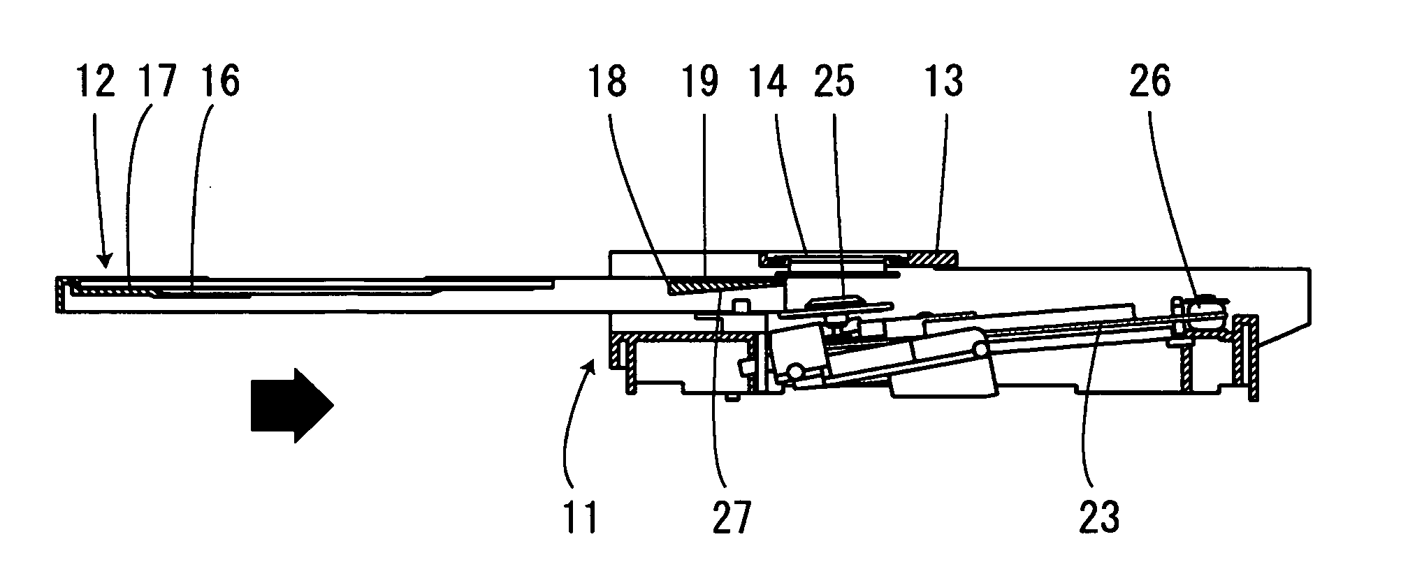
[0027] According to the eighth aspect of the present invention, in conjunction with the moving operation of the tray when making a reciprocating motion between the disk loading / ejection position and the recording / reproducing position, the chassis to which the pickup unit is attached pivots on the one end of the chassis connected to the frame of the recording and reproducing unit as a supporting point so as to be placed in an inclined position when the tray is at the disk loading / ejection position outside the information recording and reproducing device and in a horizontal position when the tray is at the recording / reproducing position, and further the inclined plane of the joint formed at the back of the tray is provided so as to be substantially parallel to the chassis in the inclined position, and therefore it is possible to more accurately detect that laser light irradiated from the pickup unit is irradiated onto the inclined plane formed on the joint of the moving tray and control the startup or stoppage of the moving tray.

Problems solved by technology

However, according to the structure described in Patent document 1, a switch is also necessary to detect to which of the disk loading / ejection position or the recording / reproducing position the tray has moved, which may cause an increase in the cost of the unit or increase in the number of man-hours for assembly work.
It is also necessary to provide a space for disposing the switch in the frame of the unit and further, the large protrusion for a trigger and the small protrusion for a trigger for pressing the switch are formed in the tray, and therefore this structure is unsuitable for downsizing of the unit.

Method used


Image

  • Recording and reproducing unit and information recording and reproducing device incorporating recording and reproducing unit
  • Recording and reproducing unit and information recording and reproducing device incorporating recording and reproducing unit
  • Recording and reproducing unit and information recording and reproducing device incorporating recording and reproducing unit

Examples


Embodiment Construction

[0036] Hereinafter, as the best mode for implementing the present invention, embodiments of the present invention will be explained with reference to attached drawings.

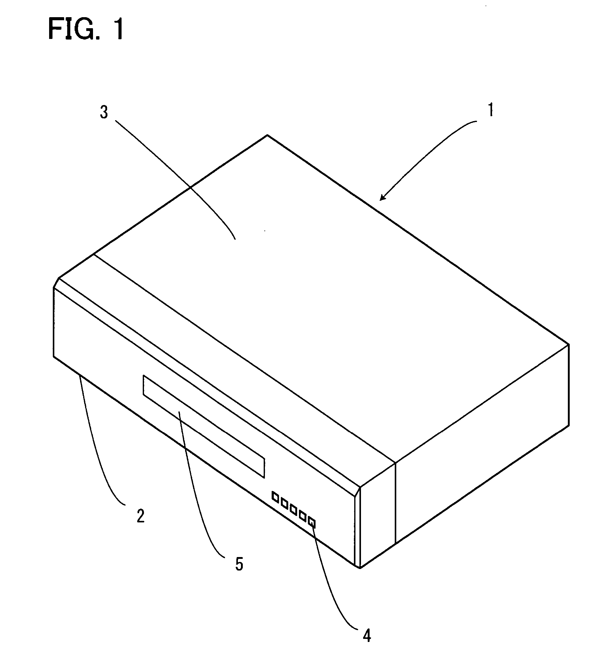
[0037]FIG. 1 is a perspective view showing the outside shape of an embodiment of an information recording and reproducing device which incorporates a recording and reproducing unit (not shown in FIG. 1) for recording and reproducing data onto / from a disk which is a storage medium of the present invention.

[0038] An information recording and reproducing device 1 is provided with an operation section 4 which made up of a plurality of operation buttons on the front side and a front panel 2 provided with a through hole 5 which allows movement of a tray, and a top plate 3 which covers the top surface and both sides and a chassis (not shown) which corresponds to the bottom side and back side behind the front side, these front panel 2, top plate 3 and chassis constituting the appearance of the apparatus.

[0039] The informat...


PUM


Abstract

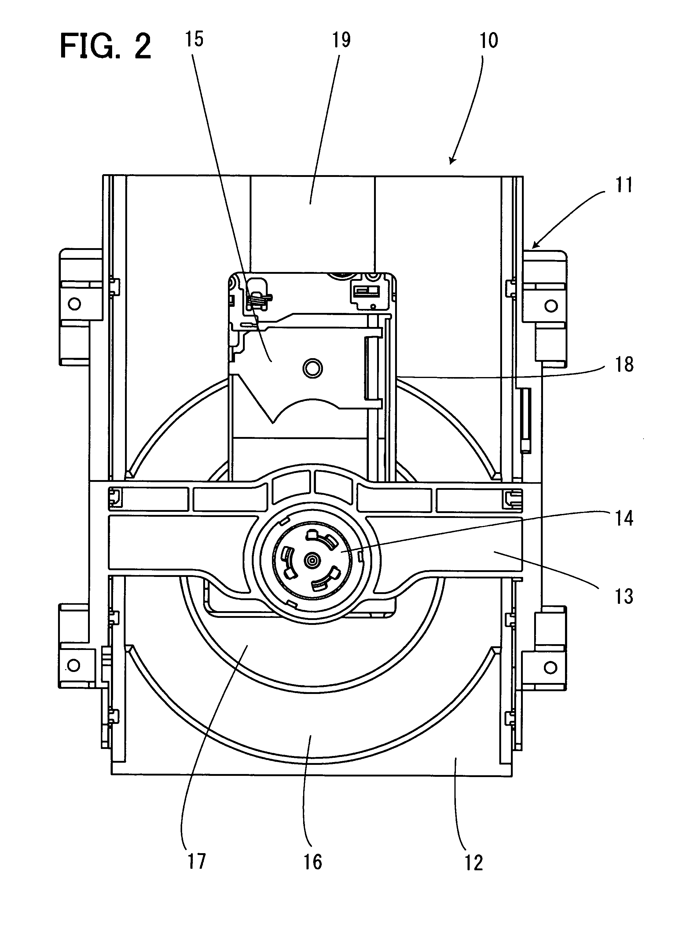
It is an object of the present invention to realize detection of a disk loading / ejection position where a disk which is a storage medium can be changed and a recording / reproducing position inside an information recording and reproducing device using an existing configuration member and thereby control the driving of a tray on which a disk is placed. A joint having an inclined plane which is irradiated with laser light irradiated from a pickup unit is formed and the laser light from the pickup unit is irradiated when the tray moves. When the tray moves between the disk loading / ejection position and the recording / reproducing position, it is detected that the laser light irradiated from pickup unit is irradiated onto the inclined plane and shielded and a motor is driven only for a preset time relative to the detected position.

Description

[0001] The present application is based on and claims priority of Japanese patent application No. 2005-160440 filed on May 31, 2005, the entire contents of which are hereby incorporated by reference. BACKGROUND OF THE INVENTION [0002] 1. Field of the Invention [0003] The present invention relates to an information recording and reproducing device which incorporates a recording and reproducing unit provided with a tray which moves with a storage medium placed thereon, and more particularly, to a type of recording and reproducing unit and information recording and reproducing device which incorporates such a recording and reproducing unit whose tray moves to the outside of the information recording and reproducing device to allow a storage medium to be changed, using a pickup unit as tray position detection means. [0004] Detection of the position of the tray to be detected in this case includes detecting that the tray has reached a disk loading / ejection position, detecting that the tr...

Claims


Application Information

Patent Timeline
IPC IPC(8): G11B17/04G11B33/02
CPCG11B17/051
Inventor NISHIDE, MASAHIKO
Owner ORION ELECTRIC CO LTD
Learn More