Drip irrigation system

a drip irrigation and drip technology, applied in the direction of applications, rigid pipes, flexible pipes, etc., can solve the problems of large water consumption, large pressure loss along the branching tubes of drip emitters, and substantial investment costs and power consumption in operation, so as to achieve low investment costs, simple assembly method, and low cost

Inactive Publication Date: 2006-12-07
NETAFIM LTD
View PDF17 Cites 18 Cited by
  • Summary
  • Abstract
  • Description
  • Claims
  • Application Information

AI Technical Summary

Benefits of technology

[0012] As an alternative embodiment, the neck of the connector may comprise a threaded portion while the second collar is formed as a separate member with internal thread matching the threaded portion so that the second collar can seal the edge of the hole to the first collar by tightening up.
[0013] According to a second aspect of the present invention, there is provided a thin-walled sleeve for use as distribution pipe, e.g. in the above irrigation system. The flow through the distribution pipe, under relatively low pressure and limited discharge through the drip emitters, is rather slow, typically between 0.02 and 0.8 m / s. Under such conditions, with conventional distribution pipes used in flood furrow irrigation, solar radiation in the field, penetrating through the pipe walls, promotes intensive growth of microorganisms and algae that are naturally present in the irrigation water. Such growth would soon lead to clogging of the drip emitters which usually have narrow water-passage labyrinths and small discharge openings. However, the distribution pipe of the present invention is made of opaque material that prevents light from entering into the pipe, thereby suppressing the growth of algae. Good results have been obtained with materials effectively stopping the visible and UV radiation and transmitting less than 5% of the IR radiation.
[0014] Another problem related to the slow water flow in the distribution pipe is heating by the sun radiation. High temperature of the water in the pipe reduces the strength of the sleeve material and accelerates aging. For this reason, the sleeve material of the present invention is not only opaque but also is designed to reflect a major part of the sun radiation, about 20% and more. Thus, the distribution pipe, even with the small flow velocity mentioned above, is not heated to more than 30-35° C. above the ambient air temperature. Notably, this problem does not exist with higher pressure pipes and with the furrow irrigation pipes where flow velocity is much higher and the running water cools the pipes.
[0015] The pipe material is extendable in the area of the holes about 1.6 times of their initial diameter, but should not be over-extendable, in order to hold the connectors up to internal pressure at least twice the operation pressure. The pipe material is also strong and deformable enough to endure overriding by wheeled vehicles with rubber tires when collapsed empty on non-rocky soil. Thus, it was found that material with total (elastic plus plastic) elongation before breaking of about 7.5 times would serve for more than one season of irrigation. Another feature of the material is that, when cut to obtain the holes, it provides accurate smooth edges of the hole.
[0033] Thus, the present invention presents an irrigation system combining the economy, controllability and environmental friendliness of known drip-irrigation systems working at higher pressure, and the low investment costs of furrow irrigation systems. The system of the present invention is especially appealing by its simple method of assembly and the possibility to use the existing sources of water used in flood irrigation like artesian wells, surface run-off waters and others. Moreover, the irrigation system of the present invention can be directly assembled on existing fields to replace flood and furrow irrigation, with no additional earth-moving works.
[0034] With the new system any flood furrow irrigation field can be upgraded for increasing irrigation uniformity from around 60% to over 80% (the 20-30% difference means saving of water and energy) in the new system, allowing to benefit from potentially higher and better yields.

Problems solved by technology

However, pressure losses along their branching tubes with drip emitters are large.
These systems involve substantial investment costs and power consumption in operation.
The flood irrigation requires less investment costs but the spending of water is huge.
Moreover, the freely flowing water causes surface erosion and salinization of soils.
However, water expenses still remain high.

Method used


Image

  • Drip irrigation system
  • Drip irrigation system
  • Drip irrigation system

Examples


Embodiment Construction

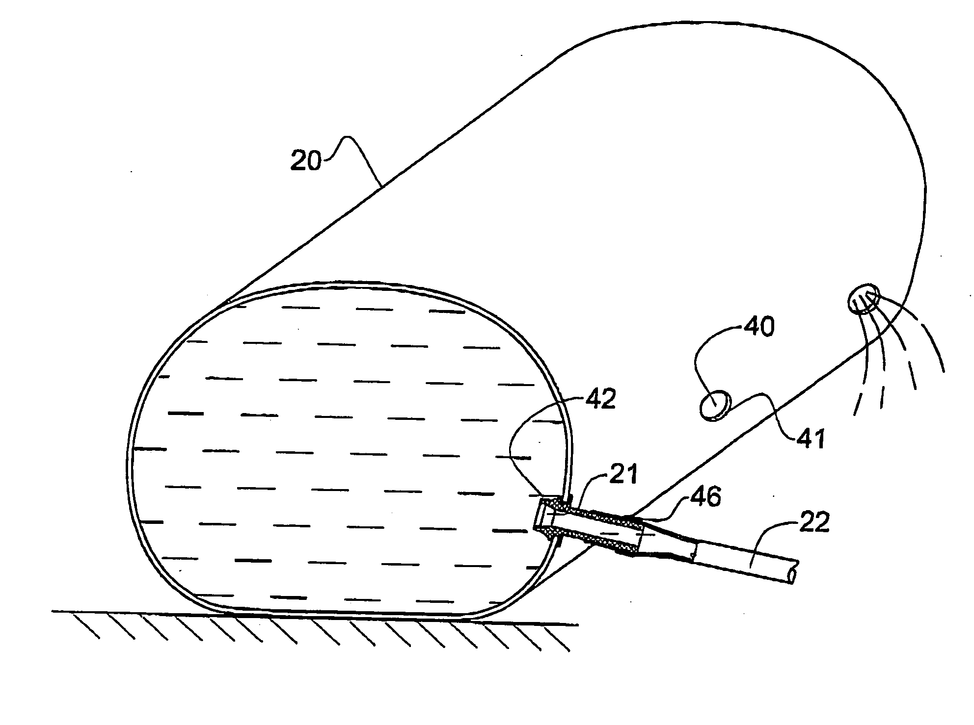
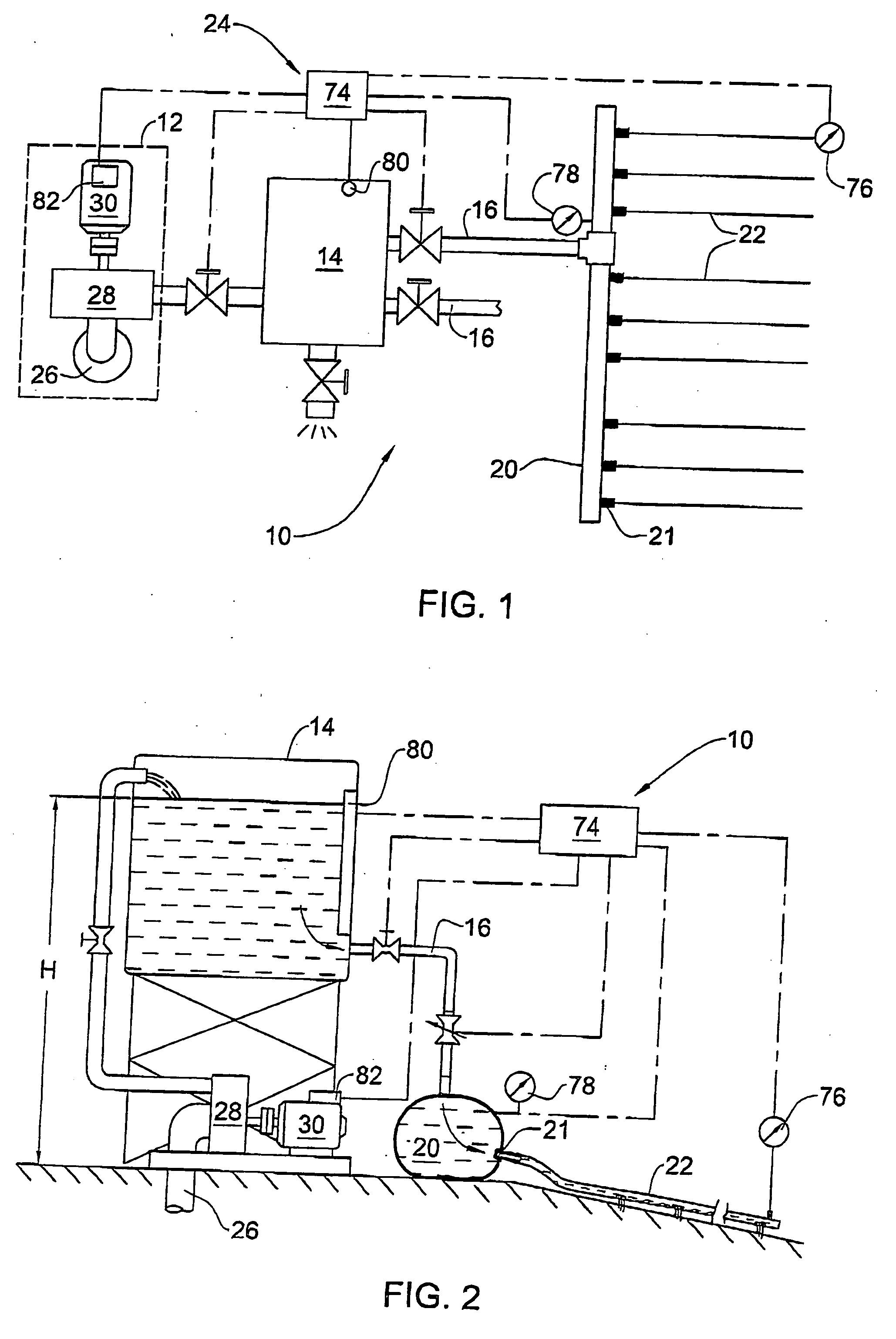
[0046] With reference to FIGS. 1 and 2, there is shown a low-pressure drip irrigation system 10, comprising a source of irrigation water 12, gravitation filter tank 14, outlet pipes 16, distribution pipes 20, connectors 21, branch tubes 22, and control system 24.

[0047] The source of irrigation water 12 in FIG. 1 is an artesian well 26 with a pump 28 and an electric drive 30, but may be any other suitable source. It is connected to the filter tank 14 which will be described in detail below. The filter tank 14 is connected to the pipes 20 by means of the outlet pipes 16.

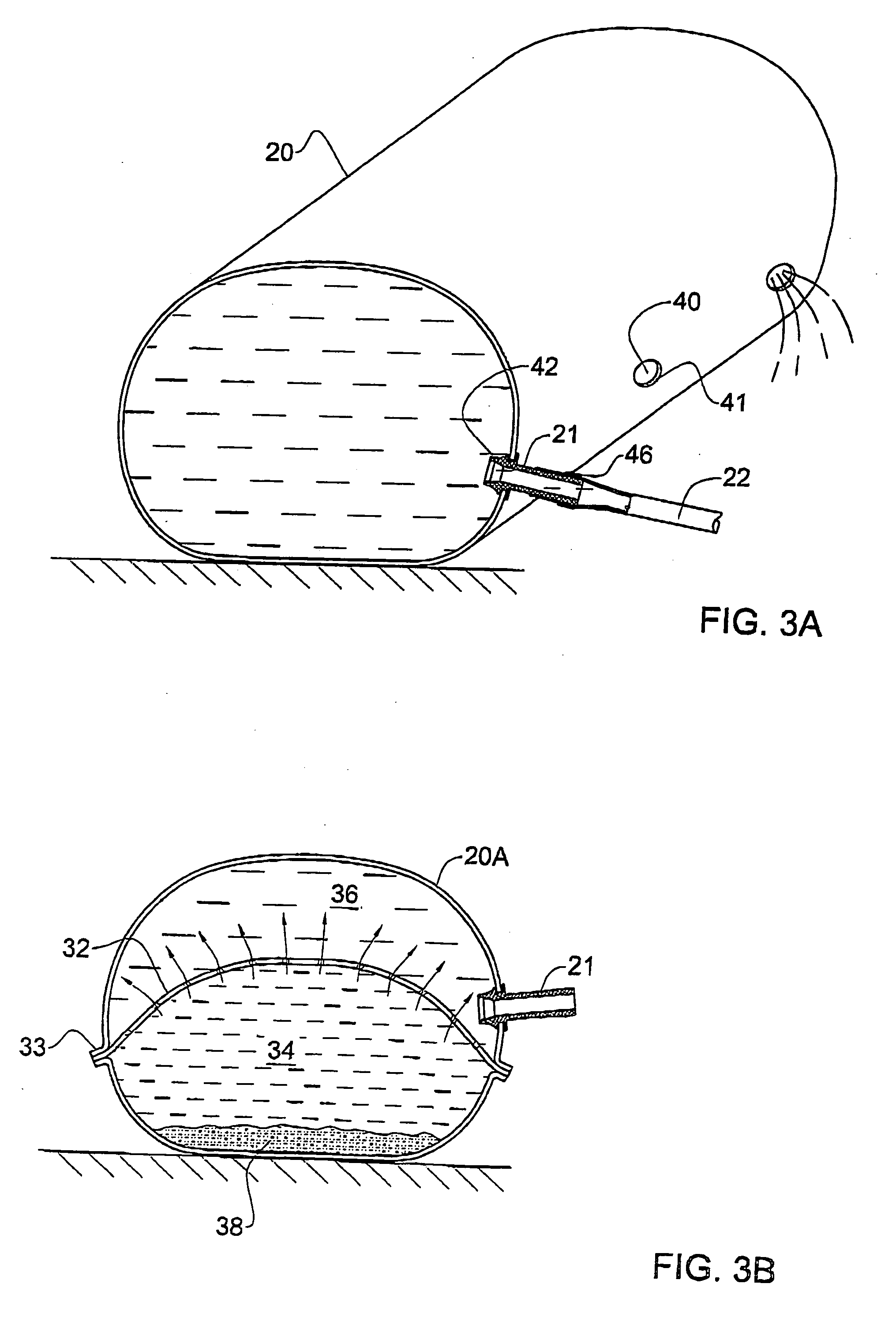
[0048] With reference also to FIG. 3A, the distribution pipe 20 has a plurality of holes 40 with edges 41 which are tightly fixed to base parts 42 of the connectors 21. The pipes 20 are used in generally horizontal state, while the branch tubes 22 may be slightly inclined, so as to maintain approximately uniform head in all drip emitters.

[0049] The distribution pipe 20 is made of thin-walled plastic collapsible slee...


PUM


Abstract

Low-pressure drip irrigation system, comprising a distribution pipe made of thin-walled sleeve collapsible when empty and designed to operate under hydraulic head up to 3 m H2O, having a plurality of holes in the walls thereof, a plurality of branch tubes equipped with low-pressure drip emitters; and a plurality of connectors connecting the branch tubes to the holes of the distribution pipe. The sleeve material is opaque and reflecting the solar radiation so that the natural growth of microorganisms and algae in the irrigation water is suppressed, and the pipe is not heated more than 35° C. above the ambient air temperature. The irrigation system is assembled in the field from components of a kit by deploying the distribution pipe, filling it with water, cutting the holes by means of a special hand-held tool, inserting the connectors into the holes, and assembling the branch tubes with the connectors.

Description

[0001] This is a division of co-pending parent application Ser. No. 10 / 431,575, filed May 8, 2003.FIELD OF THE INVENTION [0002] This invention relates to drip irrigation systems, more particularly to low-pressure irrigation systems. BACKGROUND OF THE INVENTION [0003] Known types of drip-irrigation systems use pressurized water sources of about 2 ata and more. Distribution pipes, fittings and valves in such systems are made of strong and relatively thick plastic materials. These systems are essentially independent on the field topography. However, pressure losses along their branching tubes with drip emitters are large. In order to achieve uniform dripping, special pressure-compensated emitters are used. These systems involve substantial investment costs and power consumption in operation. [0004] On the other hand, systems for flood furrow irrigation are traditionally applied on large areas. They include open distribution channels and branching furrows made in the fields. Since water...

Claims


Application Information

Patent Timeline
Patent Type & Authority Applications(United States)
IPC IPC(8): F16L11/00A01G25/02
CPCA01G25/02Y02A40/22
Inventor GOLAN, RAFIVERED, ELIMEISLESS, AMMON
Owner NETAFIM LTD
Why Eureka
Try Eureka