
Wheel for driving a flexible handrail

a technology of flexible handrails and wheels, which is applied in the direction of escalators, conveyers, transportation and packaging, etc., can solve the problems of friction, slip-stick effect, and friction to occur

Inactive Publication Date: 2006-12-07
INVENTIO AG
View PDF6 Cites 0 Cited by
  • Summary
  • Abstract
  • Description
  • Claims
  • Application Information

AI Technical Summary

Benefits of technology

[0009] The pins increase the rigidity of the enveloping cover. An enveloping cover can therefore be selected which is relatively easily elastically deformable and which therefore rests closely against the handrail with no risk of bulge formation of bulges.
[0012] The two base sheaves are usually arranged axially on opposite sides of the power transmission element. The wheel can have further base sheaves that are arranged adjacent to, or with a gap between, the first-mentioned base sheaves. The base sheaves guide the power transmission element at its sides or grip the power transmission element and prevent its lateral displacement.
[0015] Especially to facilitate the installation and any necessary replacement of individual pins, it has proved advantageous to execute the cutouts as breakthroughs of the base sheave. It is preferable for such slit-like cutouts to start at the outer circumferential surface and to be directed toward the axis of rotation.
[0016] Important advantages of the new wheel include prevention of the slip-stick effect between the wheel and the handrail and prevention of bulge formation in the contact area of the wheel and handrail.
[0019] If the slip-stick effect is avoided, the creation of noise is reduced to the extent that it depends on the energy that is freed on transition from static friction to sliding friction. If the formation of bulges is reduced, the creation of noise is reduced to the extent that it depends on the resulting vibrations. At the same time, wear of the respective J components and the power required for driving are reduced while ride comfort is increased.

Problems solved by technology

Slip-stick effects are instability effects associated with parameters which affect the static friction and sliding friction between the handrail and the contact surface of the wheel that drives the handrail.
In practice, however, it is common for brief periods of sliding friction to occur, which is comparable to aquaplaning and results in the slip-stick effect.
Disadvantageous with such a driving wheel is, among others, the formation of bulges on the driving-wheel tire, which occurs as a consequence of its elasticity, as well as substantial wear of the tire through use.

Method used


Image

  • Wheel for driving a flexible handrail
  • Wheel for driving a flexible handrail
  • Wheel for driving a flexible handrail

Examples


Embodiment Construction

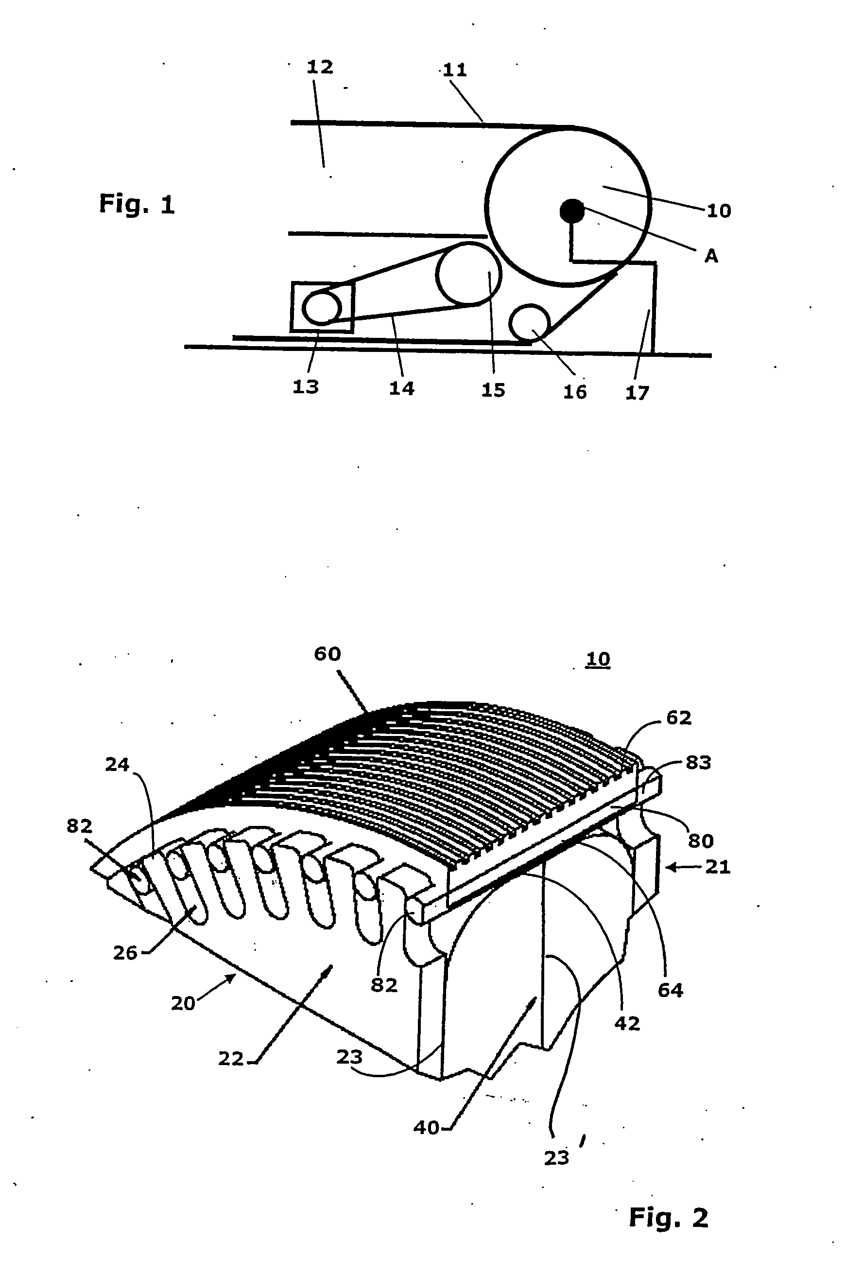
[0026]FIG. 1 shows a wheel 10 according to the invention that can be turned about an axis of rotation A and drives a handrail 11. The handrail 11 is located on the upper edge of a balustrade 12 that is arranged at the side of not-shown step elements of the escalator or moving walk. The handrail 11 lies longitudinally at almost 180° to the wheel 10. Drive of the wheel 10 takes place, for example, by means of a motor 13 via an endless element 14 and a drive wheel 15. A diverter pulley 16 is also provided for the handrail. The wheel 10 is fastened in a conventional manner to a locationally fixed supporting construction 17.

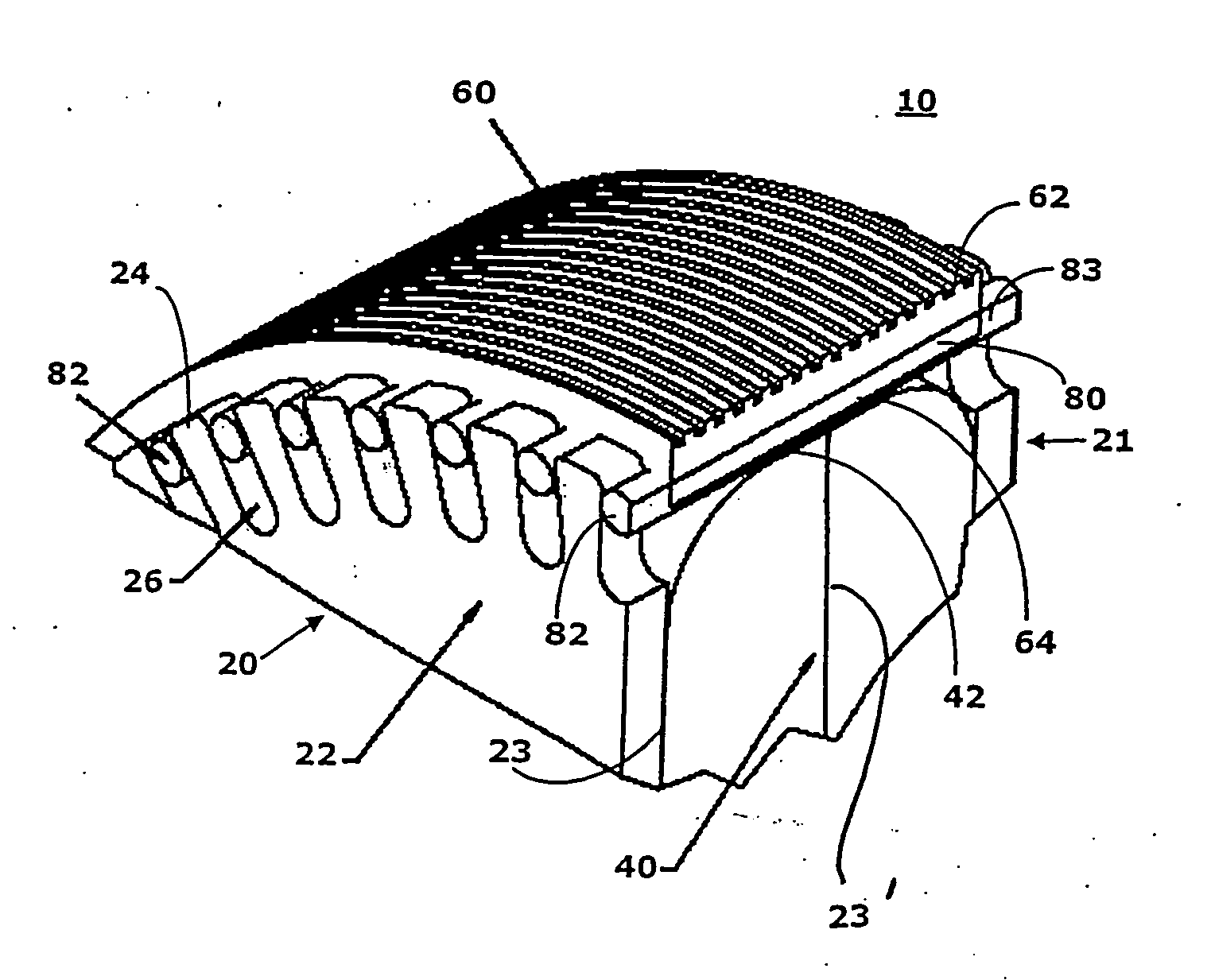
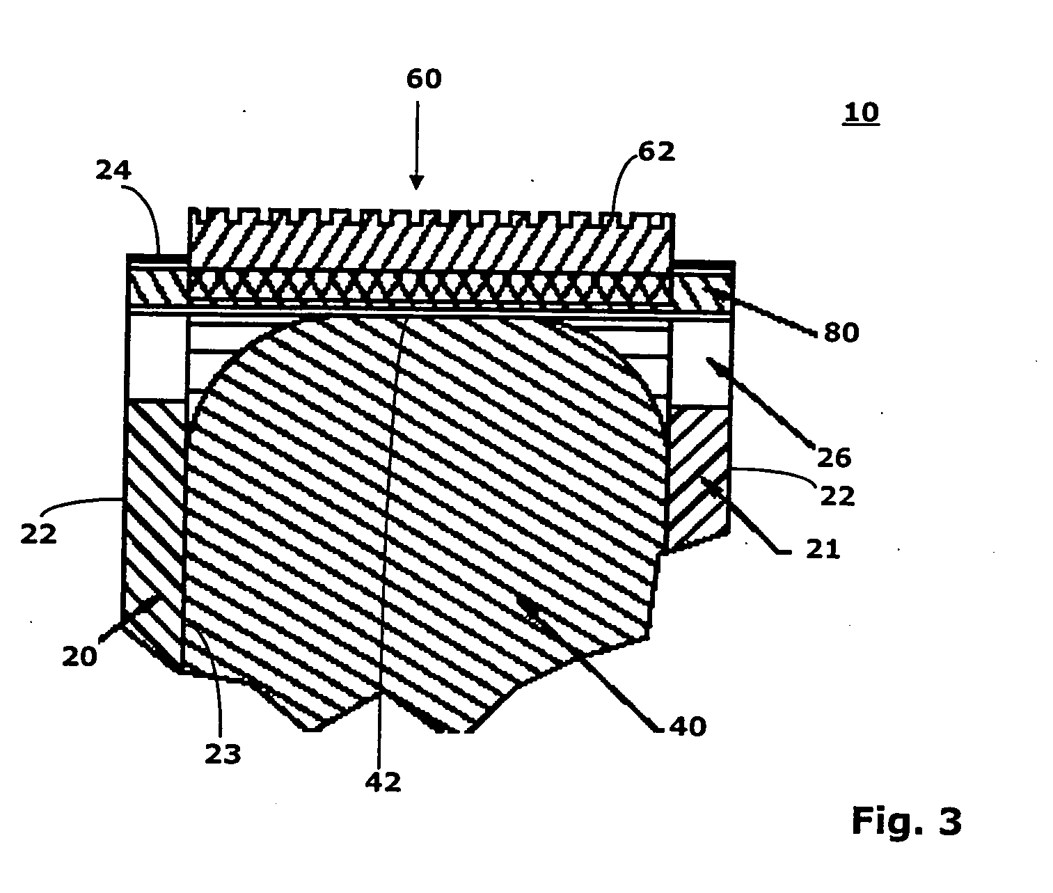
[0027] According to FIGS. 2 and 3 the wheel 10 has two base sheaves 20, 21, a power transmission element 40, an enveloping cover 60, and a plurality of pins 80. The wheel 10 can be either directly or indirectly motor driven and serves to drive the flexible handrail 12 of the escalator or moving walk, which is guided on the circumference of the wheel 10. The handrail ...


PUM


Abstract

A wheel for driving a flexible handrail of an escalator or moving walk. The wheel has a power transmission element that can be turned about an axis of rotation and that has, on its circumference a contact surface through which an outwardly acting radial force can be exerted. The wheel also has two base sheaves that are arranged coaxially to the power transmission element. Each base sheave has a plurality of slits that are arranged in the outer edge area of the base sheave and extend toward the axis of rotation. The slits of one base sheave form, with the slits of the other base sheave, slit pairs. The wheel has a circumferential cover with an inside surface against which the contact surface of the power transmission element rests. A plurality of pins is arranged in the circumferential cover, each pin engaging a separate respective slit pair.

Description

[0001] The present invention relates to a wheel for driving a flexible handrail of an escalator or moving walk. BACKGROUND OF THE INVENTION [0002] Escalators and moving walks generally have balustrades that are locationally fixed at their sides. Mounted on or against the balustrades are band-shaped handrails that move relative to the balustrades as synchronously as possible with the step elements of the escalator or moving walk. The handrails consist essentially of a flexible band and can be driven by a wheel that can itself be driven directly or indirectly by a motor. At the same time, the wheel can also serve the function of a diverter sheave to divert the handrail where a change of direction of the handrail is required. [0003] The drive of handrails should be as smooth and continuous as possible, free of jerks, as quiet as possible, and the wheel as well as the handrail itself should be constructed in such a manner that noise and wear are minimized. In particular, so-called slip-...

Claims


Application Information

Patent Timeline
Patent Type & Authority Applications(United States)
IPC IPC(8): B66B23/22
CPCB66B23/04B66B23/02
Inventor NOVACEK, THOMASILLEDITS, THOMAS
Owner INVENTIO AG
Learn More