
Method of, and apparatus for, measuring the quality of a printed image

Inactive Publication Date: 2006-12-07
GALTON DAVID JOHN +1
View PDF20 Cites 1 Cited by
  • Summary
  • Abstract
  • Description
  • Claims
  • Application Information

AI Technical Summary

Benefits of technology

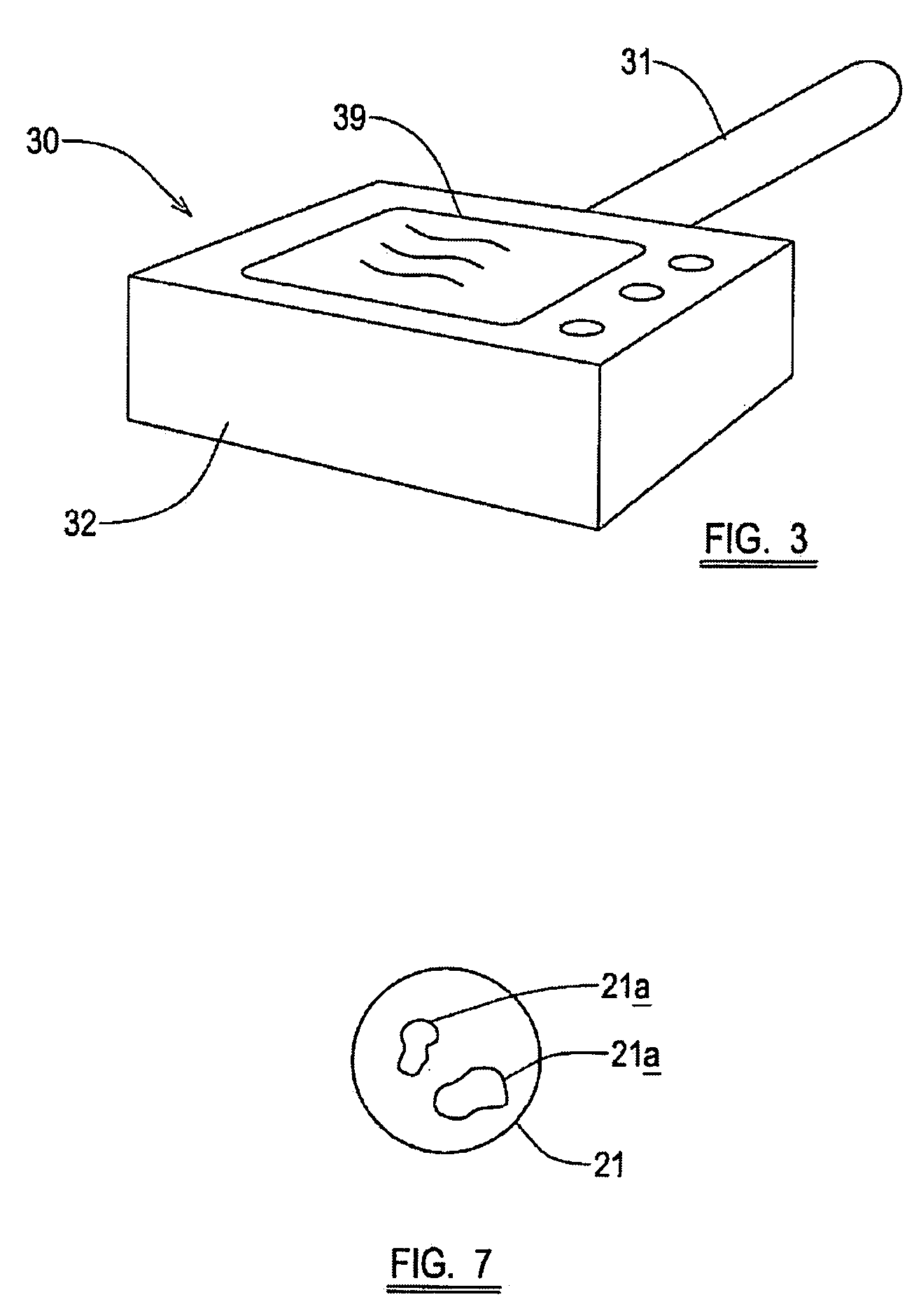
[0025] The image obtaining apparatus may be hand-held and may, for example, obtain a digital full-color high resolution image of the pattern. This has the advantage that a user can use the apparatus to assess the quality of a printed image at any time after the image has been printed, e.g. before or after the printed image has been transported from a location where it was printed.
[0026] Alternatively, the image obtaining apparatus may be an integral part of a printing apparatus which prints the image onto the substrate, in which case the image obtaining apparatus may be configured to acquire a digital image of th

Problems solved by technology

However, the plurality of test elements are of such detail that changes in

Method used


Image

  • Method of, and apparatus for, measuring the quality of a printed image
  • Method of, and apparatus for, measuring the quality of a printed image
  • Method of, and apparatus for, measuring the quality of a printed image

Examples


Embodiment Construction

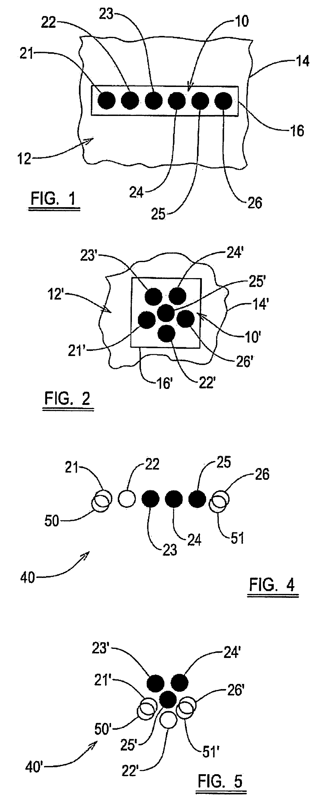
[0046] Referring to FIG. 1, this shows a magnified plan view of a pattern 10 of a plurality of test elements in accordance with the present invention. The pattern 10 is produced by a plurality of formations provided on a printing member, e.g. a printing plate (not shown), which is supported on a rotatable drum (also not shown) of a printing apparatus within a periphery of a plurality of formations defining an image 12 to be printed onto a substrate 14. The size of the pattern 10 is such that when the image 12 is printed, the pattern 10 is hidden from casual visual inspection of the printed image 12, thus ensuring it does not spoil the overall impression of the printed image 12. The location of the pattern 10 is, however, known by an operator of the printing apparatus (or any other appropriate third party wishing to check the quality of the image), so that he / she can use the pattern 10 to measure the quality of the printed image 12.

[0047] Alternatively, the printing member may be in...


PUM


Abstract

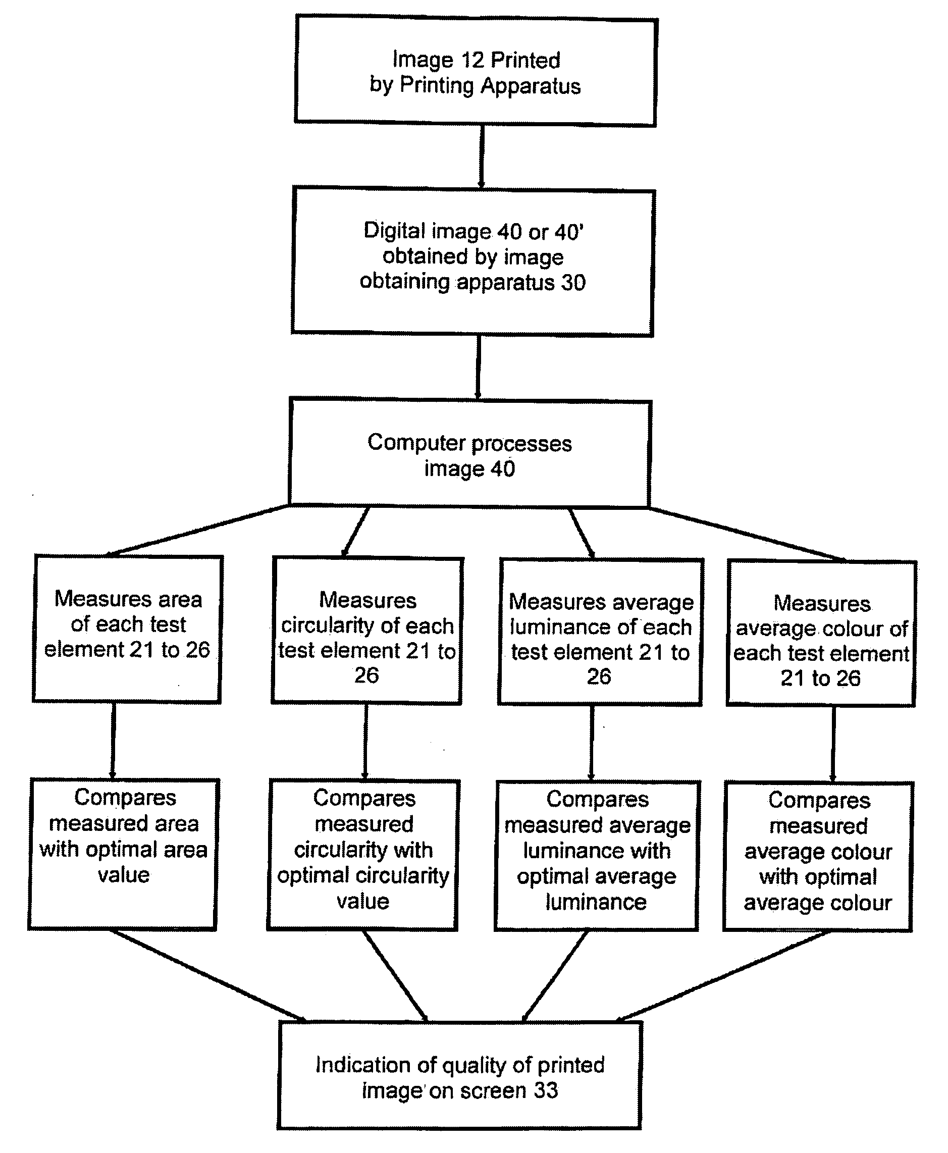
A method of measuring the quality of a printed image, including the steps of: providing a substrate with a printed image thereon; obtaining a digital image of a part of the printed image using an image obtaining apparatus; and measuring one or more physical characteristics of the obtained digital image so as to provide an indication of the quality of the printed image.

Description

CROSS-REFERENCE TO RELATED APPLICATIONS [0001] Applicants claim priority to U.S. Provisional Patent Application Ser. No. 60 / 681,700 filed May 17, 2005.STATEMENT REGARDING FEDERALLY SPONSORED RESEARCH OR DEVELOPMENT [0002] Not Applicable. TECHNICAL FIELD [0003] This invention relates to a method of, and apparatus for, measuring the quality of a printed image. BACKGROUND OF THE INVENTION [0004] Printed images created using conventional presses, such as Rotogravure (Intaglio), Flexographic and Lithographic (Offset) presses, require the adjustment of many variables to create a suitable, high quality, e.g. up to 4500 dpi (dots per inch), reproduction of the original subject material. The adjustment of these variables, such as, pressure, ink viscosity and temperature, is commonly the responsibility of the press operator, who employs subjective evaluation of the quality of the printed image and adjusts these variables accordingly until the quality of the printed image is satisfactory. [000...

Claims


Application Information

Patent Timeline
IPC IPC(8): G01R31/28
CPCB41F33/0036B41P2233/52G01N21/25G01N2201/0221H04N1/00002H04N1/00087H04N1/00031H04N1/00045H04N1/00063H04N1/00076H04N1/00015
Inventor GALTON, DAVID JOHNROSENBERGER, ROY R.
Owner GALTON DAVID JOHN
Learn More