Obstacle detection device for vehicle
a technology for detecting devices and obstacles, applied in measurement devices, using reradiation, instruments, etc., to achieve the effect of reducing the number of wirings and the cost of connection
- Summary
- Abstract
- Description
- Claims
- Application Information
AI Technical Summary
Benefits of technology
Problems solved by technology
Method used
Image

Examples
first embodiment
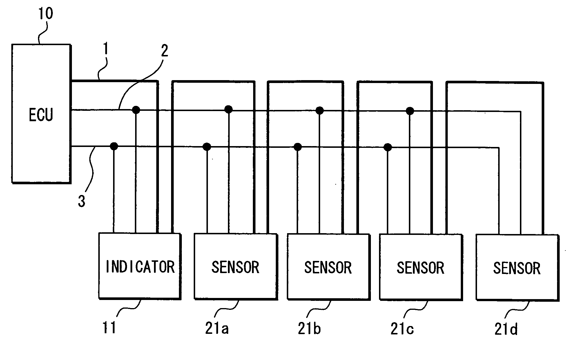
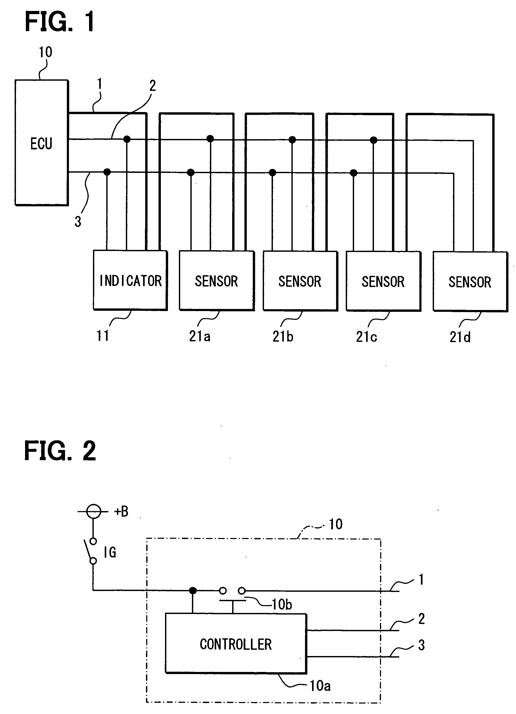
[0030] An obstacle detection device for a vehicle according to a first embodiment of the present invention will be described with reference to FIGS. 1-8. As shown in FIG. 1, the obstacle detection device includes an informing unit 11 (e.g., indicator), multiple obstacle detection units (e.g., sensors 21a-21d) and a control unit 10 (e.g., ECU), which is connected with the informing unit 11 and the obstacle detection units.
[0031] The ECU 10 controls operations of the sensors 21-21d and the indicator 11, which are connected with a communication line 3. Specifically, for example, the ECU 10 controls (instructs) the sensors 21a-21d so that the sensors 21a-21d send signals (e.g., ultrasound pulse signals) for detecting an obstacle to the exterior at a predetermined timing. Moreover, obstacle position information detected by each of the sensors 21a-21d is sent to the indicator 11, to be indicated by the indicator 11.
[0032] The ECU 10 provides (sets) ID for the indicator 11 and the sensor...
second embodiment
[0068] According to the above-described first embodiment, the indicator 11 is directly connected with the communication line 3, and the ID setting of the indicator 11 and the operation control of the indicator 11 is performed via the communication line 3. However, the communication line 3 will become long, for example, in the case where the ECU 10 is mounted near the center portion of the vehicle, the indicator 11 is mounted near the driver seat and the sensors 21a-21d are arranged at the rear bumper. That is, the communication line 3 will become long due to the mounting positions of the ECU 10, the indicator 11 and the sensors 21a-21d.
[0069] According to a second embodiment of the present invention, the indicator 11 is indirectly connected with the communication line 3 via a lead 6 which is drawn from the communication line 3. That is, the indicator 11 is not directly connected with the communication line 3. The ID setting of the indicator 11 and the control of the indicator 11 ar...
third embodiment
[0103] According to the above-described first and second embodiments, the ID setting of the indicator 11 and the sensors 21a-21d is performed after the indicator 11 is mounted at the vehicle.
[0104] According to a third embodiment of the present invention, referring to FIG. 14, the indicator 11 where the ID is beforehand set before being mounted at the vehicle can be also used. In this case, the ID setting for the sensors 21a-21d is performed after the indicator 11 is mounted at the vehicle, similarly to what described above.
[0105] According to the third embodiment, the indicator 11 can be connected to the communication line 3 at the foremost stage or the final stage of the communication line 3. Alternatively, the indicator 11 can be also connected to the communication line 3 via the lead line, as described in the second embodiment. Thus, the same effects with those of the first embodiment or the second embodiment can be obtained.
[0106] In the third embodiment, what has not been d...
PUM
 Abstract
Description
Claims
Application Information
 - R&D
- Intellectual Property
- Life Sciences
- Materials
- Tech Scout
- Unparalleled Data Quality
- Higher Quality Content
- 60% Fewer Hallucinations
Browse by: Latest US Patents, China's latest patents, Technical Efficacy Thesaurus, Application Domain, Technology Topic, Popular Technical Reports.
© 2025 PatSnap. All rights reserved.Legal|Privacy policy|Modern Slavery Act Transparency Statement|Sitemap|About US| Contact US: help@patsnap.com