Apparatus and methods for making leaflets and valve prostheses including such leaflets

a technology of valve prosthesis and apparatus, which is applied in the field of apparatus and methods for making bioprosthetic valve assemblies, can solve the problems of adversely affecting the hemodynamic performance of the valve, the die cutter may have difficulty punching or otherwise forming holes near or adjacent to the leaflet, and the leaflet hemodynamic performance is affected. to achieve the effect of accurate and/or precise sealing of the leafl

Active Publication Date: 2006-12-07
MEDTRONIC INC
View PDF21 Cites 71 Cited by
  • Summary
  • Abstract
  • Description
  • Claims
  • Application Information

AI Technical Summary

Benefits of technology

[0008] The present invention is directed generally to prosthetic valve assemblies and to apparatus and methods for making them, and, more particularly, to apparatus and methods for forming leaflets, e.g., from biological tissue, and / or for securing leaflets to a frame or other support structure using alignment holes formed in the leaflets, e.g., to make prosthetic valve assemblies. The alignment holes may accurately and / or precisely secure the leaflets to the support structure using standard suturing techniques. The present invention is also directed to leaflet laminate components, valve members, and other structures, and to apparatus and methods for assembling them.

Problems solved by technology

The variation in which the sutures are placed in the valve may adversely impact the hemodynamic performance of the leaflets after they are secured to the support structure.
Variability is thus introduced within a single valve (e.g. intra-valve variability), which may adversely impact the valve's hemodynamic performance.
This latter problem may arise, for example, because a number of different persons are employed to affix the individual leaflets to support structures or otherwise assemble the valves.
When such leaflets are formed from bovine pericardium or other biological tissue, a die cutter may have difficulty punching or otherwise forming holes near or adjacent to the edge of the leaflets.

Method used


Image

  • Apparatus and methods for making leaflets and valve prostheses including such leaflets
  • Apparatus and methods for making leaflets and valve prostheses including such leaflets
  • Apparatus and methods for making leaflets and valve prostheses including such leaflets

Examples


Embodiment Construction

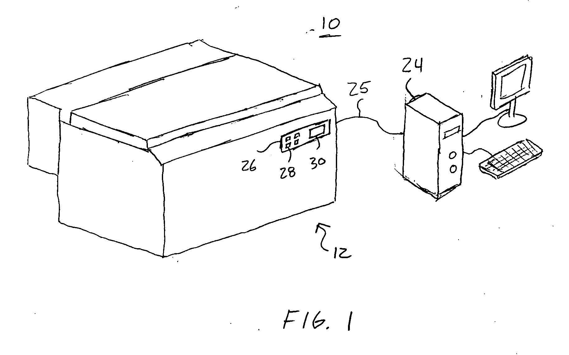
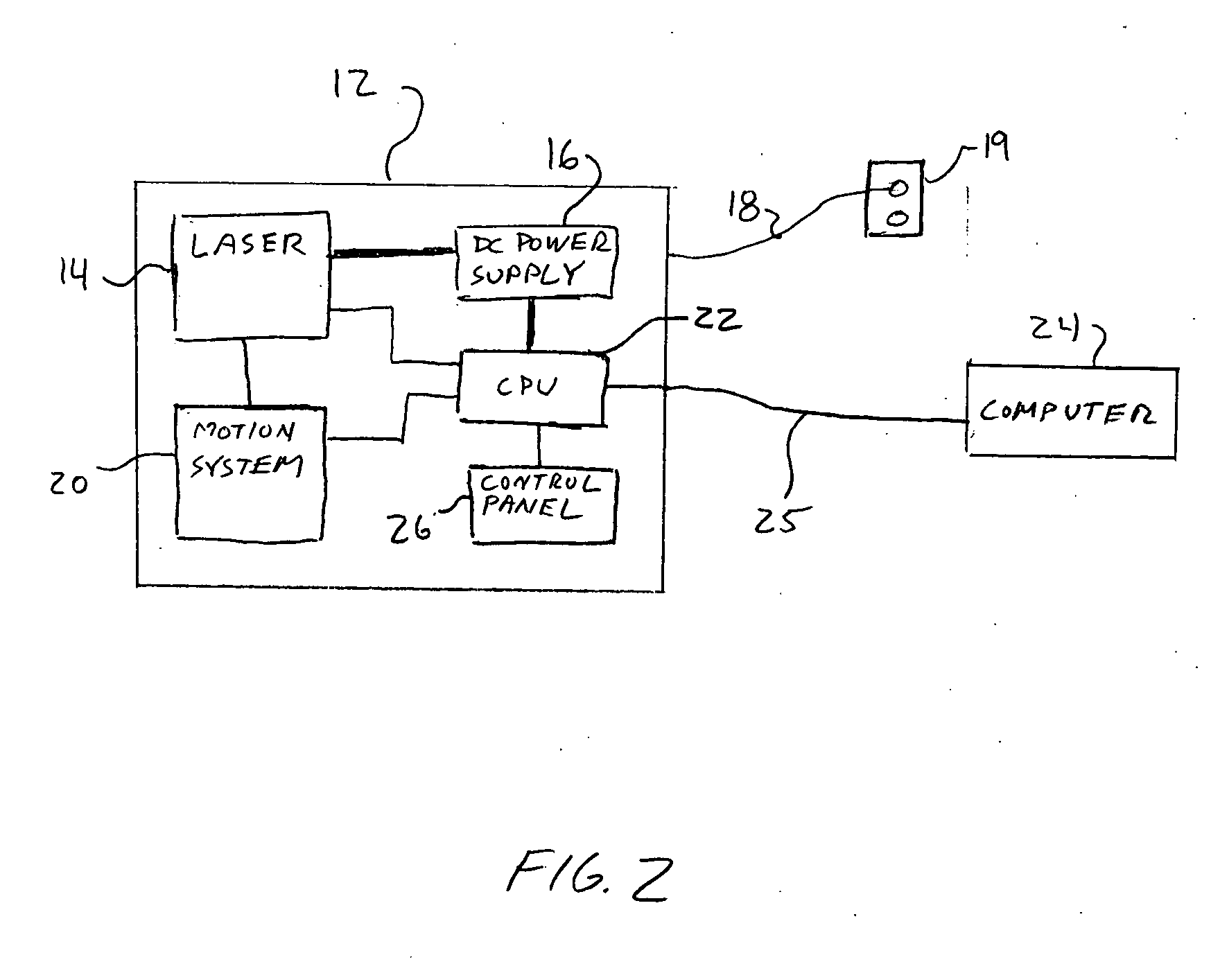
[0025] Turning to the drawings, FIGS. 1 and 2 show an exemplary embodiment of a cutting apparatus 10, i.e., a computer controlled laser system 12. As best seen in FIG. 2, the laser system 12 includes a laser source 14 powered by a DC power supply 16, which in turn, is connected to an AC power cord 18. The AC power cord 18 may be plugged into a standard 110 / 220 VAC outlet 19 or other power source (not shown). The laser source 14 may be a pulsed laser source, such as a pulsed CO2 laser operating at a wavelength of 10.6μ. The DC power supply 16 may power the laser source 14, as well as the other electronic components of the laser system 12.

[0026] The laser system 12 includes a motion system 20 that enables the laser beam 38 (not shown, see, e.g., FIG. 3) emitted from the laser source 14 to traverse or follow a pre-determined path to cut a target material 34, such as biological tissue. In an exemplary embodiment, the motion system 20 may move in both X and Y directions (see, e.g., FIG....


PUM


Abstract

A method for making a bioprosthetic heart valve includes providing a non-contact cutting apparatus and a layer of tissue. The non-contact cutting apparatus may include a laser cutting system or high pressure water jet system. A leaflet is cut from the layer of tissue using a predefined template, and a plurality of alignment holes in the leaflet are created in the leaflet, e.g., along a peripheral edge. A support structure is provided having a plurality of alignment holes corresponding to alignment holes in the leaflet. The leaflet is secured to the support structure by securing one or more sutures through corresponding alignment holes in the leaflet and the support structure to provide a leaflet subassembly. A bioprosthetic heart valve is made by securing a set of leaflet subassemblies to a frame.

Description

FIELD OF THE INVENTION [0001] The present invention relates generally to apparatus and methods for making bioprosthetic valve assemblies, and more particularly, to apparatus and methods for forming valve leaflets including alignment holes, e.g., from biological tissue, and for assembling such leaflets into laminate assemblies and / or prosthetic heart valves. BACKGROUND [0002] Bioprosthetic heart valves can replace defective native or previous prosthetic valves in patients. Bioprosthetic heart valves generally include a plurality of leaflets attached or otherwise coupled to a frame, stent, or other support structure. The leaflets may be formed from a synthetic material or biological tissue, such as bovine pericardium. [0003] Sutures may be used to secure the leaflets to the support structure of the valve. Typically, a person, such as physician or even a specially trained seamstress, uses a needle and suture thread to pass one or more sutures through the leaflet and the support structu...

Claims


Application Information

Patent Timeline
Patent Type & Authority Applications(United States)
IPC IPC(8): A61F2/24
CPCA61F2/2412Y10S623/901A61F2220/0075A61F2/2415
Inventor LEE, SHOUYANLANE, ERNEST
Owner MEDTRONIC INC
Why Eureka
Try Eureka