Method and apparatus for predicting branch instructions

a branch history and instruction technology, applied in the field of microprocessors, can solve the problems of limiting the ability to realize further branch prediction performance gains, large branch history tables generally are not accessible quickly enough, and untimely availability, and achieve the effect of significant flexibility in configuring the size and accuracy of the second branch history tabl

Active Publication Date: 2006-12-07
QUALCOMM INC
View PDF6 Cites 14 Cited by
  • Summary
  • Abstract
  • Description
  • Claims
  • Application Information

AI Technical Summary

Benefits of technology

[0010] In one or more embodiments, a microprocessor uses a first branch history table to predict branch instructions that are branch target cache hits, and uses a second branch history table to predict branch instructions that are branch target cache misses. The first branch history table is configured to have an access speed matched to that of the branch target cache, so that its prediction information is available early in the microprocessor's instruction pipeline, where branch target cache hits and misses are detected. Because its prediction information is not needed until later in the pipeline, the second branch history table does not need to be as fast as the first branch history table. That fact allows significant flexibility in configuring the size and accuracy of the second branch history table.

Problems solved by technology

The attendant delays limit the ability to realize further branch prediction performance gains through the use of branch target address caches (or, equivalently, branch target instruction caches).
Large branch history tables generally are not accessible quickly enough for use in predicting branch target cache hits.
The unavailability of timely prediction information forces microprocessors to adopt other approaches.
Such approaches can lead to mispredictions a significant number of times. Another alternative is to speed up the branch history table, typically by making it small enough to be accessible early in the instruction pipeline's fetch stage(s), so that prediction information is available before instruction decoding.
However, shrinking the branch history table in this manner generally reduces prediction accuracies because the same predictor (or predictors) is used to predict branches over a wider range of instruction addresses.

Method used


Image

  • Method and apparatus for predicting branch instructions
  • Method and apparatus for predicting branch instructions
  • Method and apparatus for predicting branch instructions

Examples


Embodiment Construction

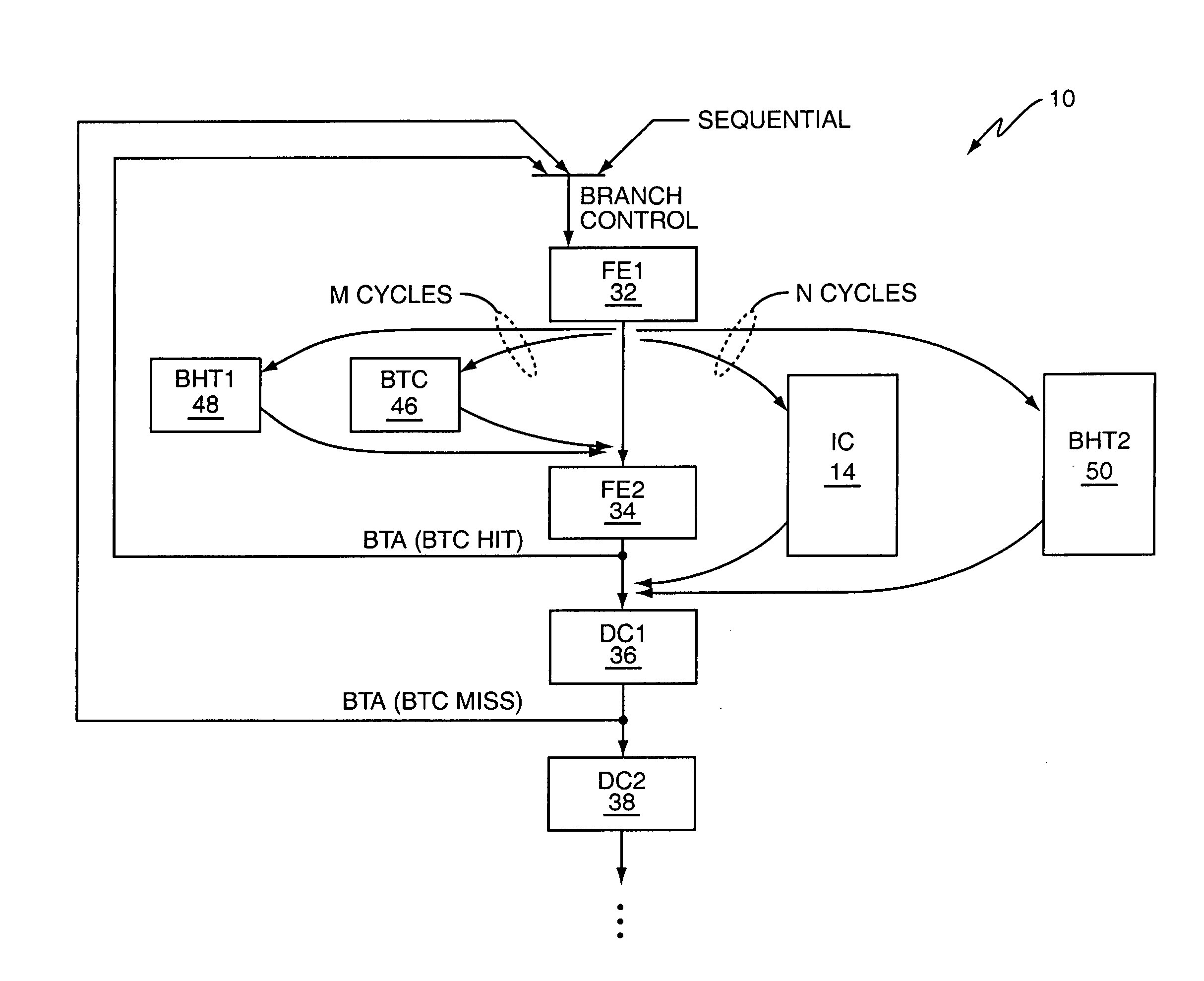
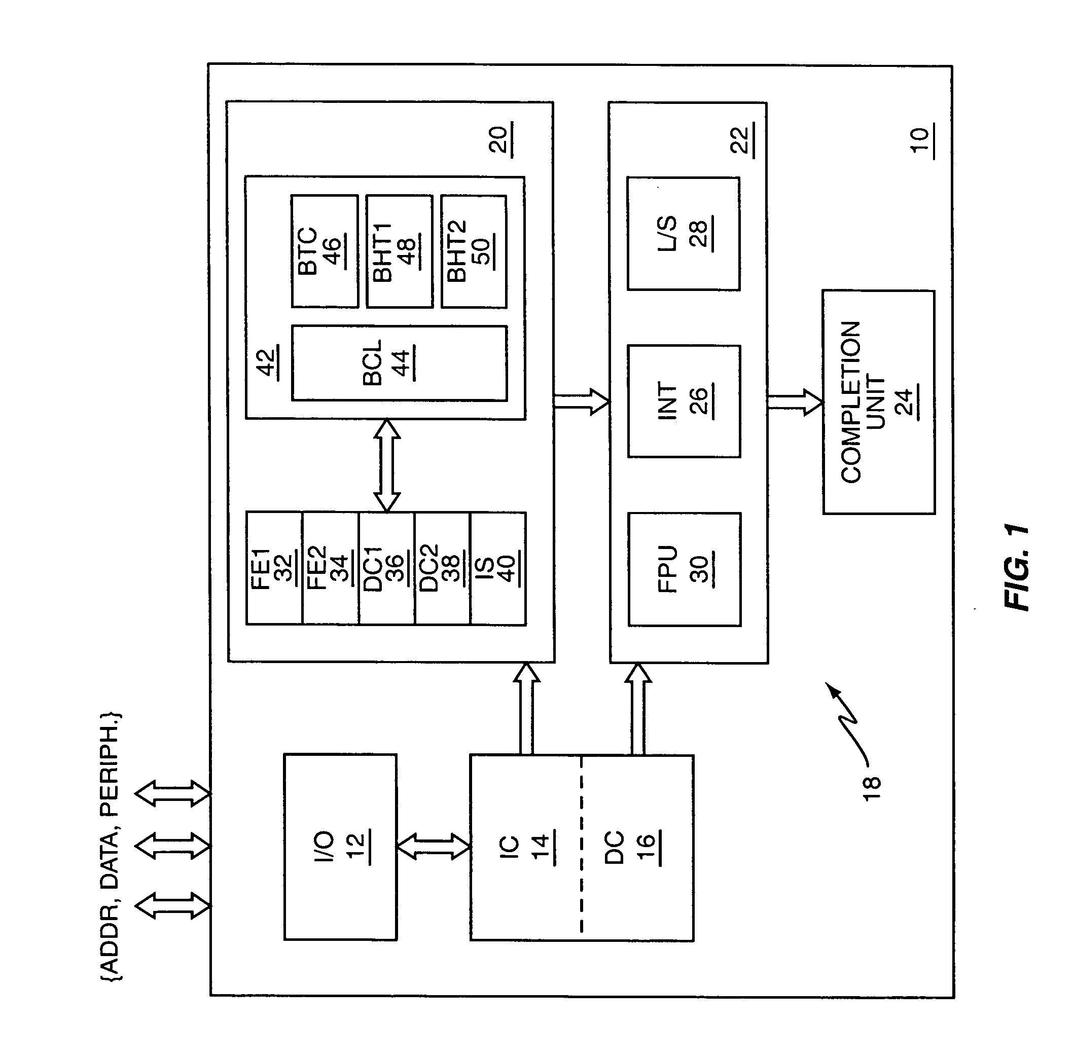
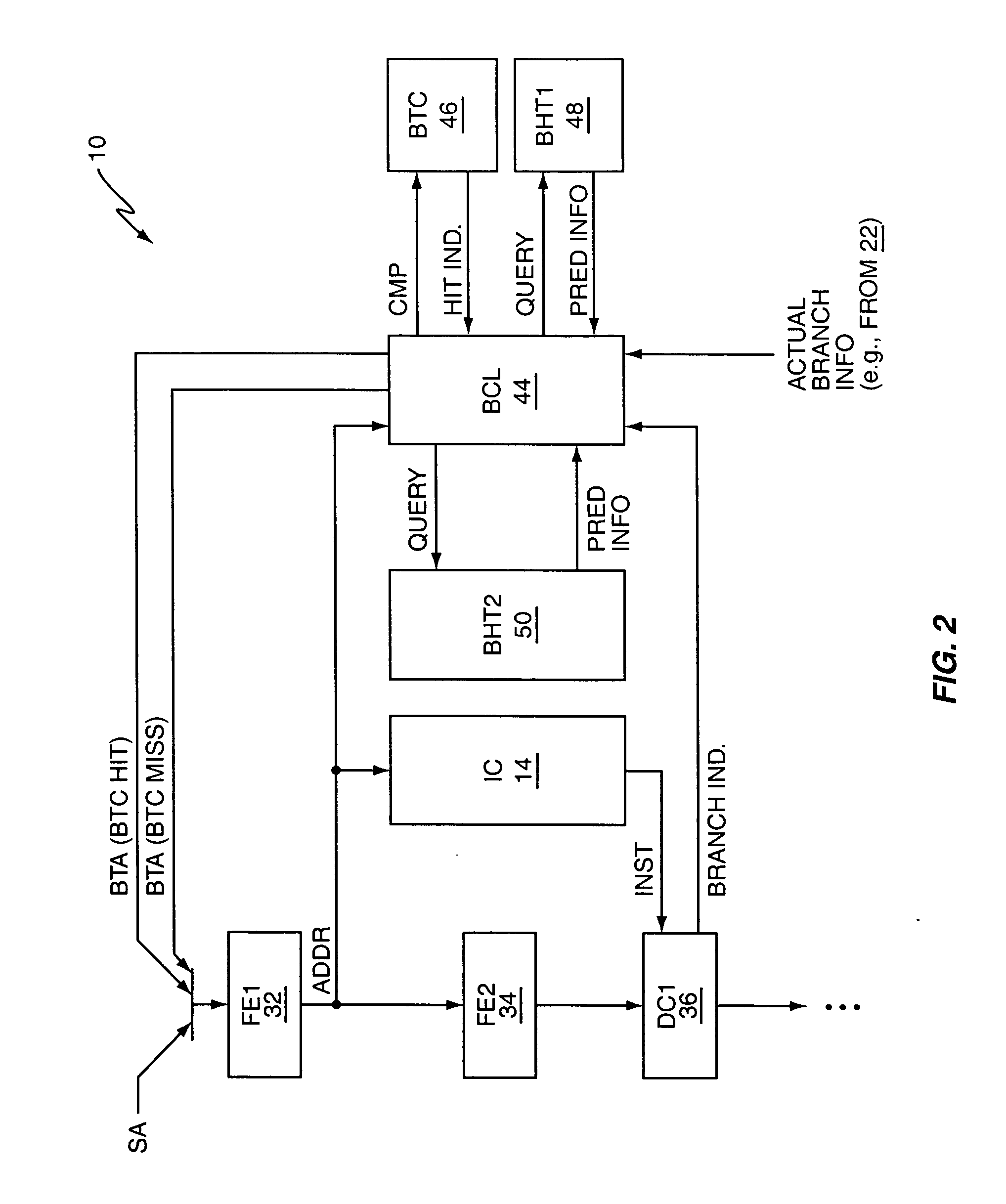
[0019] By way of non-limiting example, FIG. 1 illustrates a microprocessor 10, which may comprise a pipelined RISC microprocessor. In the illustrated embodiment, the microprocessor 10 comprises input / output (I / O) circuits 12, an instruction cache 14, a data cache 16, and an instruction pipeline 18, which comprises a front-end circuit 20, an execution unit 22, and a completion unit 24.

[0020] In operation, the front-end circuit 20 fetches instructions from the instruction cache 14, which may be an on-board Level 1 (L1) cache. The instructions are fetched according to a defined computer program flow, which may include program branches or jumps. The microprocessor 10 uses branch prediction to predict whether conditional branches will be taken or not taken, such that it generally does not interrupt its instruction fetching operations when conditional branch instructions are encountered.

[0021] Fetched instructions are decoded and issued to the execution unit 22, which can be implemented...


PUM


Abstract

A microprocessor includes two branch history tables, and is configured to use a first one of the branch history tables for predicting branch instructions that are hits in a branch target cache, and to use a second one of the branch history tables for predicting branch instructions that are misses in the branch target cache. As such, the first branch history table is configured to have an access speed matched to that of the branch target cache, so that its prediction information is timely available relative to branch target cache hit detection, which may happen early in the microprocessor's instruction pipeline. The second branch history table thus need only be as fast as is required for providing timely prediction information in association with recognizing branch target cache misses as branch instructions, such as at the instruction decode stage(s) of the instruction pipeline.

Description

BACKGROUND [0001] 1. Field of the Invention [0002] The present invention generally relates to microprocessors, and particularly relates to branch predicting microprocessors. [0003] 2. Relevant Background [0004] Pipelined microprocessors commonly use branch prediction to avoid stalling their instruction pipelines while waiting to determine whether conditional branch instructions should be taken. Branch prediction mechanisms allow such microprocessors to “guess” as to whether conditional branch instructions will be taken or not taken, in advance of actually evaluating their branch conditions. [0005] A common branch prediction method relies on maintaining a branch history table that includes a number of saturated counters, or other tracking indicators, that provide branch prediction information. As one example, a two-bit saturated counter counts up to a maximum value of 11, and down to a minimum value of 00, where the value 11 represents strongly taken, 10 represents weakly taken, 01 r...

Claims


Application Information

Patent Timeline
Patent Type & Authority Applications(United States)
IPC IPC(8): G06F9/44
CPCG06F9/3844
Inventor SARTORIUS, THOMAS ANDREWSTEMPEL, BRIAN MICHAELBRIDGES, JEFFREY TODDDIEFFENDERFER, JAMES NORRISSMITH, RODNEY WAYNE
Owner QUALCOMM INC
Why Eureka
Try Eureka