Malfunction monitoring method and system
- Summary
- Abstract
- Description
- Claims
- Application Information
AI Technical Summary
Benefits of technology
Problems solved by technology
Method used
Image

Examples
Example
[0044] A first embodiment of the present invention will be described hereinafter with reference to FIGS. 1 to 11. In the first embodiment, malfunction monitoring method and system are applied to an ECU 100 for controlling in-vehicle devices.
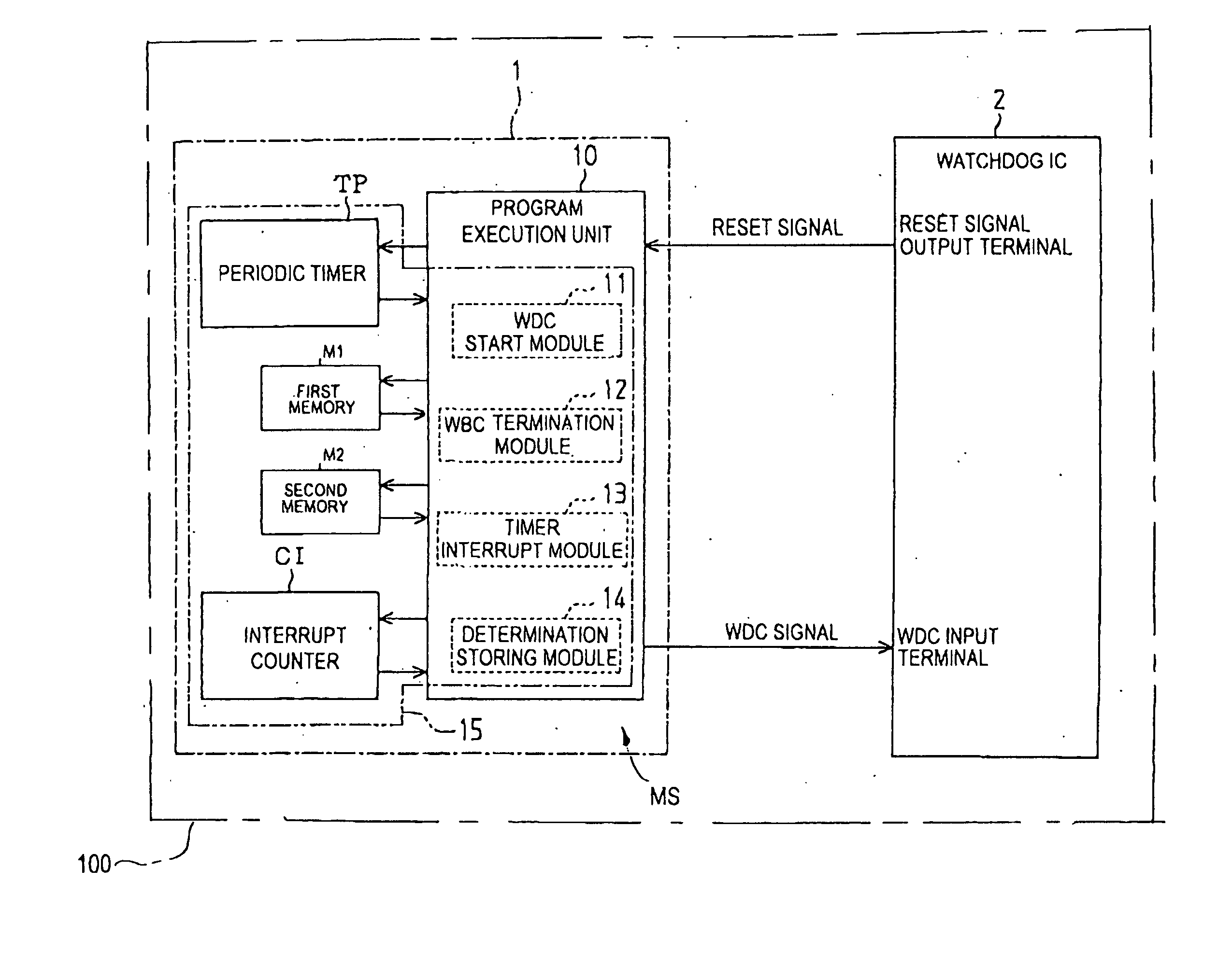
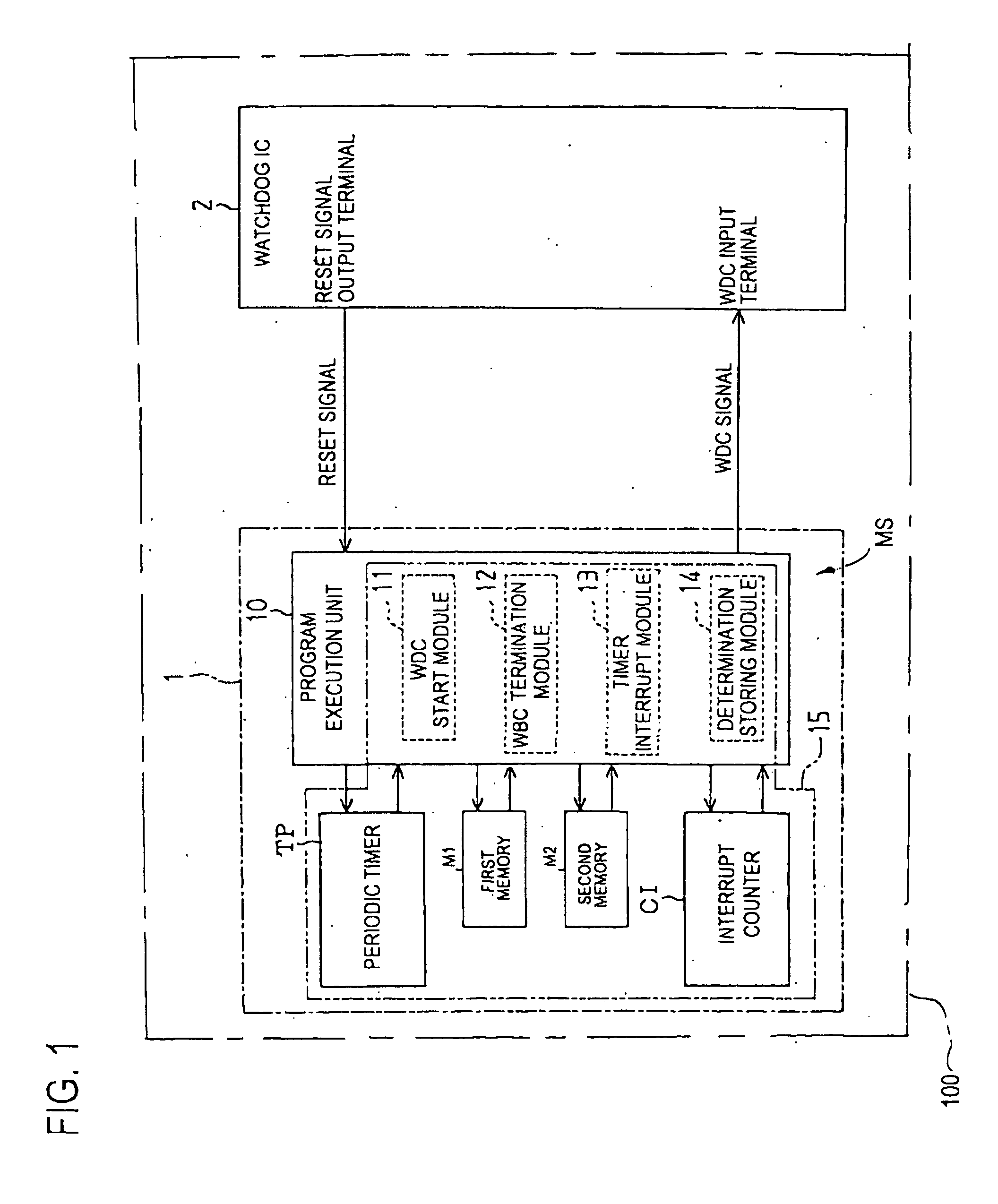
[0045] Referring to the drawings, in which like reference characters refer to like parts in several views, particularly to FIG. 1, there is illustrated the ECU 100 in which a malfunction monitoring system MS has been installed according to the first embodiment.
[0046] The malfunction monitoring system MS is configured to monitor execution of a program of a microcomputer 1 installed in the ECU 100 through a watchdog IC 2 installed therein. The malfunction monitoring system MS is also configured to enable the watchdog IC 2 to reboot the microcomputer 1 to prompt the program if it is determined that the microcomputer 1 is presumed to be malfunctioning, such as the program is interrupted or hung.
[0047] An example of the structure of the malfunction...
Example
[0141] A second embodiment of the present invention will be described hereinafter with reference to FIGS. 1, 4, 5, and 12 to 17. Note that the hardware structure of the malfunction monitoring system according to the second embodiment will be substantially identical with that of the malfunction monitoring system MS according to the first embodiment.
[0142] The malfunction monitoring system according to the second embodiment is configured to calculate individually first and second determination values based on periods within which the initialization program and off-task program are presumed to be completed, respectively.
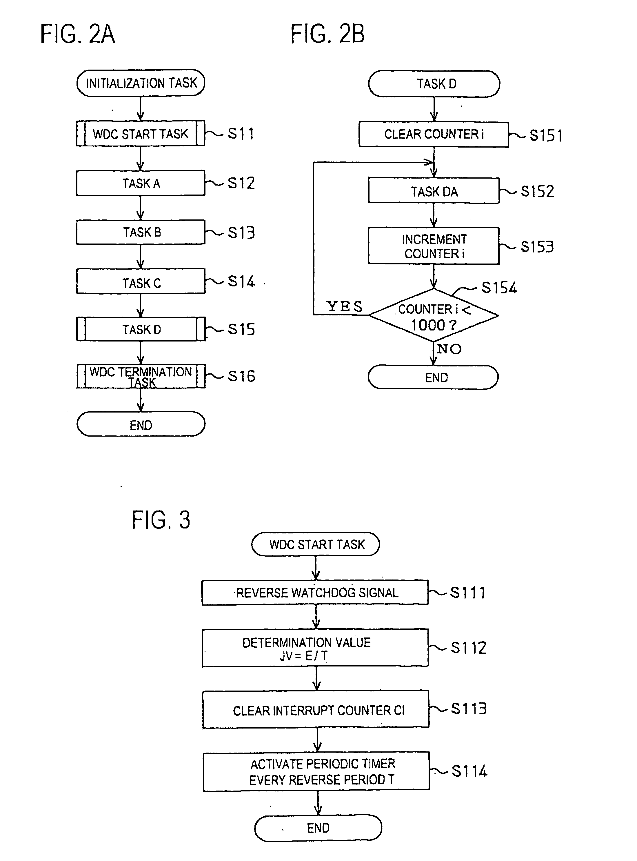
[0143] For example, in the second embodiment, the initialization program consists of a plurality of sequential tasks A1 to D1, and the off-task program consists of a plurality of sequential tasks A2 to D2. Like the first embodiment, each of the tasks D1 and D2 includes steps S151 to S154 illustrated in FIG. 2B, but the descriptions of the task DA are different from ea...
Example
Third embodiment
[0187] A third embodiment of the present invention will be described hereinafter with reference to FIGS. 1, 15, 17, and 18. Note that the hardware structure of the malfunction monitoring system according to the third embodiment will be substantially identical with that of the malfunction monitoring system MS according to the first embodiment.
[0188] The malfunction monitoring system according to the third embodiment is configured to change the determination value based on an execution time of a task that is presumed upon execution of the task.
[0189] For example, in the third embodiment, the task C2 in the off-task program causes the program execution unit 10 to write a failure code(s) into the second memory M2 if a failure occurs during execution of the normal task programs for controlling the in-vehicle devices. The failure code(s) is designed to identify the occurrence of the failure.
[0190] Next, the task C2 to be executed by the program execution unit 10 in acc...
PUM
 Abstract
Description
Claims
Application Information
 - R&D Engineer
- R&D Manager
- IP Professional
- Industry Leading Data Capabilities
- Powerful AI technology
- Patent DNA Extraction
Browse by: Latest US Patents, China's latest patents, Technical Efficacy Thesaurus, Application Domain, Technology Topic.
© 2024 PatSnap. All rights reserved.Legal|Privacy policy|Modern Slavery Act Transparency Statement|Sitemap