Flexible clamping apparatus for medical devices

a technology for clamping apparatus and medical devices, which is applied in the direction of instruments, scaffold accessories, signs, etc., can solve the problems of limited design of existing pole clamps, occupying a large amount of vertical space for pumps mounted by conventional pole clamps, and not allowing two or more degrees of freedom of movement of pumps

Active Publication Date: 2006-12-14
CARDINAL HEALTH IRELAND UNLTD
View PDF84 Cites 45 Cited by
  • Summary
  • Abstract
  • Description
  • Claims
  • Application Information

AI Technical Summary

Benefits of technology

[0006] In another aspect, a powered medical device assembly capable of selective mounting on a support generally comprises a powered medical device capable of use in at least one of diagnosing, monitoring and treating a patient. The medical device includes a housing and a display screen. A flexible shaft is adapted for connection to the medical device at a first end of the shaft and is adapted for connection to the support at a second end of the shaft. The flexible shaft is selectively configurable while connected to the medical device and to the support to permit the medical device to be moved from a first position in which the medical device is retained by the flexible shaft so that a point on the medical device is a first distance away from the support to a second position in which the medical device is retained by the flexible shaft so that the point on the medical device is a second distance different from the first distance from the support.

Problems solved by technology

However, existing pole clamp designs do not permit two or more degrees of freedom of motion of the pump such that the pump may be moved horizontally, vertically, or laterally relative to the IV pole for easier viewing and operation of the pump.
As such, the pumps mounted by conventional pole clamps take up a large amount of vertical space on the IV pole that may be needed for other devices and / or medical fluid containers.
Furthermore, some existing pole clamp designs are limited in that they allow secure attachment of the feeding pump to a vertical cylindrical support structure such as an IV pole but cannot be readily mounted on other support structures such as a horizontal table top.
Even if the clamp could be attached to some horizontal structure (e.g., a horizontally extending bed rail), the medical device would not be oriented properly for use.
Such existing pole clamps do not allow an enteral feed pump or other medical device to be used outside of a hospital or medical care facility where vertical IV poles are unavailable and cumbersome for use.

Method used


Image

  • Flexible clamping apparatus for medical devices
  • Flexible clamping apparatus for medical devices
  • Flexible clamping apparatus for medical devices

Examples


Embodiment Construction

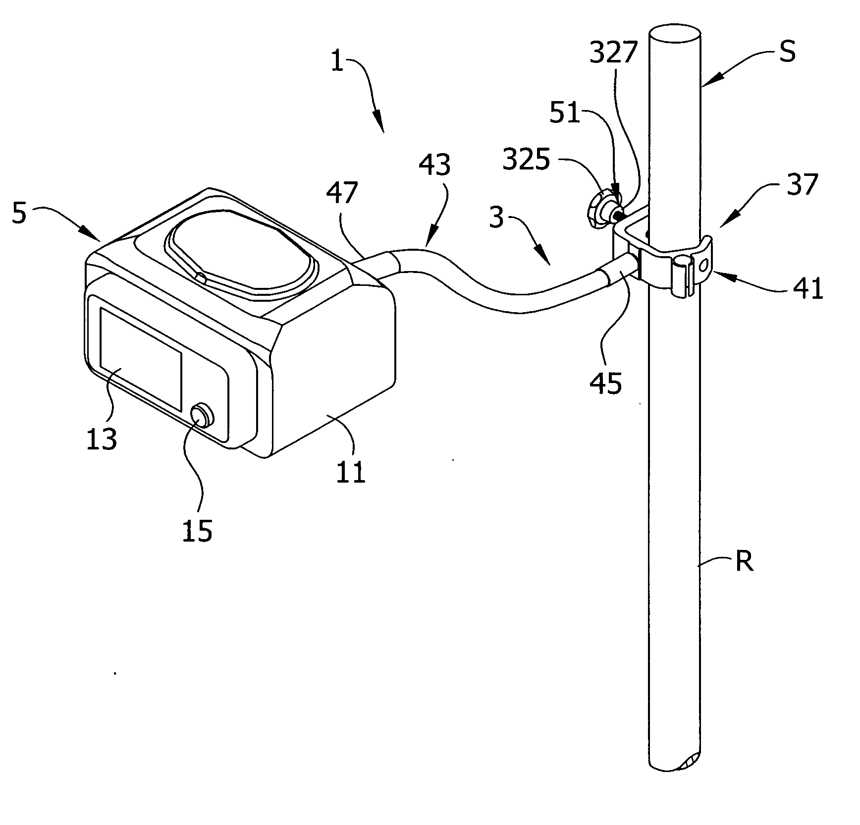
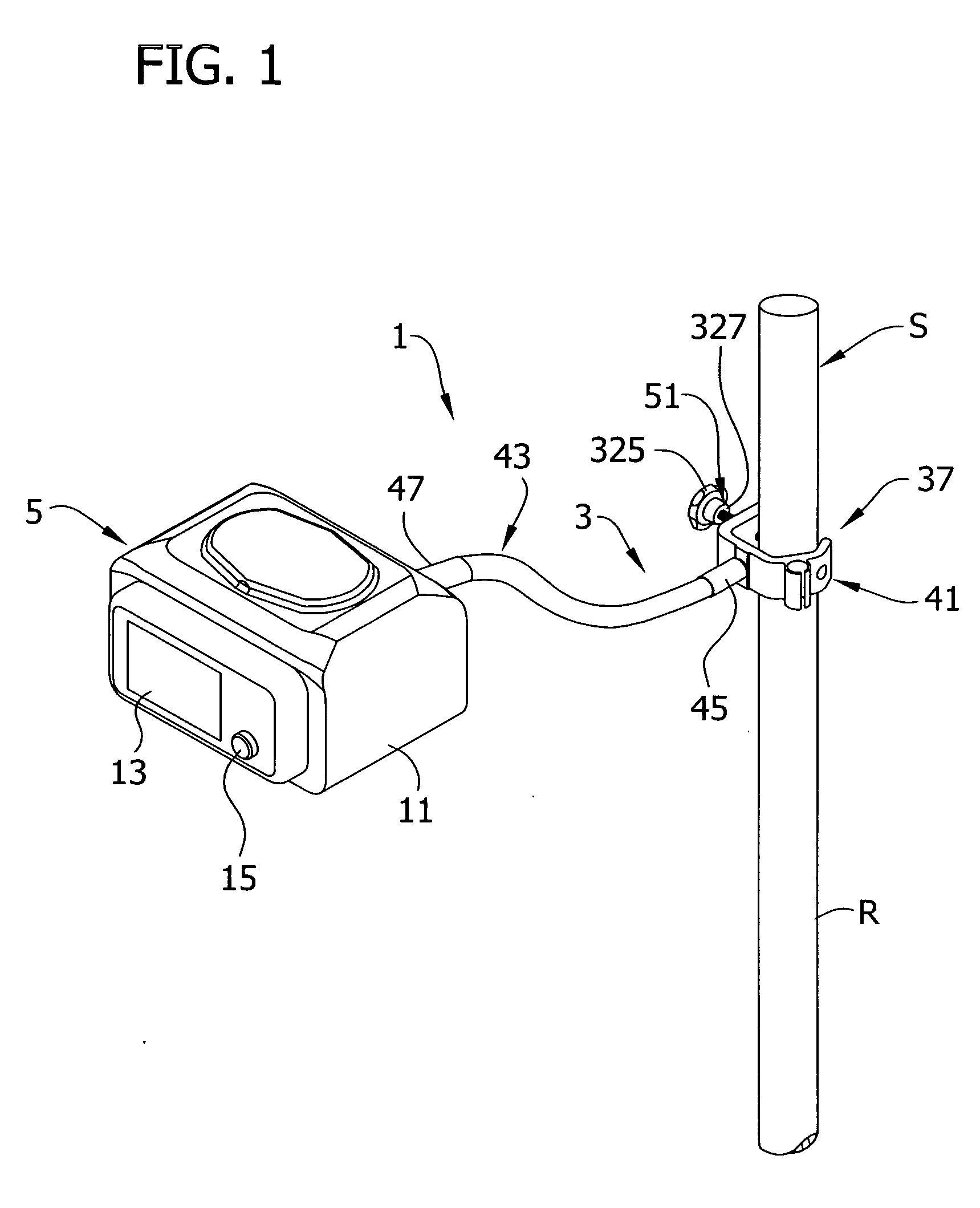
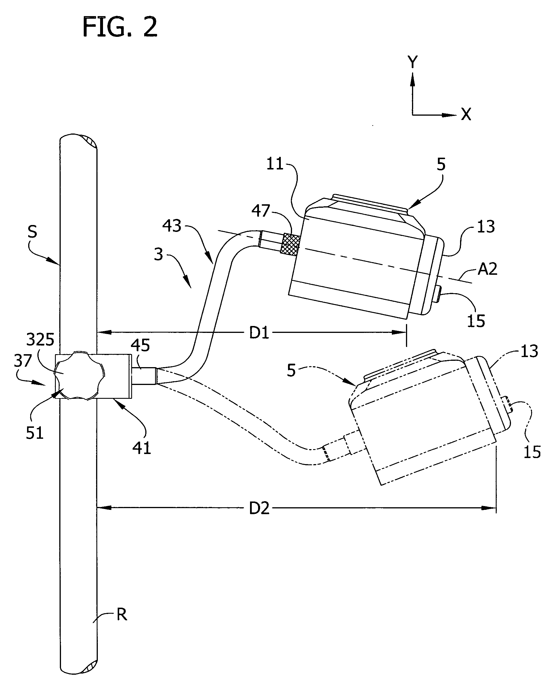
[0028] Referring now to the drawings and in particular to FIGS. 1 and 2, a powered medical device assembly 1 includes a clamping apparatus 3 releasably attached to a support member S to support a medical device 5 on the support member (the reference numerals designating their subjects generally). In the embodiment of FIG. 1, the support member S is a vertical IV pole (broadly, “a support member) having a cylindrical rod R extending up from a stand (not shown) that is commonly used to support medical paraphernalia such as IV bags (not shown) in a hospital or other healthcare environment. As discussed further below, the clamping apparatus 3 is capable of mounting the medical device 5 on support members having other than cylindrical shapes. The clamping apparatus 3 is configured to allow full range of motion (i.e., six-degrees of freedom of motion) of the medical device 5 relative to the support member S so the medical device can be positioned for better viewing and adjustment. The cla...


PUM


Abstract

A mounting apparatus (3) of the present invention is used in a medical environment to releasably secure a device (5) to a support member (S; R; PS). The mounting apparatus (3) has a flexible shaft (43; 125; 139; 279) with a first end (45; -; -; 275) for releasable attachment to the support member (S; R; PS) and a second end (47; 131; -; -) for releasable attachment to the device (5). A generally C-shaped clamping member (41; 217; 273) at the first end (45; -; -; 275) releasably attaches the apparatus (3) to the support member (S; R; PS). The clamping member (41; 217; 273) has an inner surface (161; -; 317), an outer surface (165; 225; 301), and at least two apertures including a first aperture (177, 199; -; -) through which a securing rod (51) passes and a second aperture (179; -; 315) for releasable attachment of the flexible shaft (43; 125; 139; 279). The present invention is also directed to a powered medical device assembly (1) having a medical device (5) and a flexible shaft (43; 125; 139; 279) capable of selective mounting of the medical device (5) on a support (S; R; PS).

Description

BACKGROUND OF THE INVENTION [0001] This invention relates generally to the field of support apparatus for medical devices and more particularly to a medical device mounting apparatus having a flexible shaft. [0002] Medical devices such as enteral feeding pumps are typically attached to an IV pole or other support member by a pole clamp or other attachment device that holds the pump in a fixed position relative to the support member. One existing pole clamp design allows one degree of freedom of motion of the pump relative to the pole by allowing the pump to be rotated or indexed between fixed orientations relative to the IV pole. However, existing pole clamp designs do not permit two or more degrees of freedom of motion of the pump such that the pump may be moved horizontally, vertically, or laterally relative to the IV pole for easier viewing and operation of the pump. [0003] Such existing pole clamps are typically mounted directly on the housing of the pump so that the pump housin...

Claims


Application Information

Patent Timeline
Patent Type & Authority Applications(United States)
IPC IPC(8): A47B96/06
CPCA61M5/1415A61M2209/08F16B2/065F16M11/40F16M2200/027F16M11/10F16M11/24F16M13/022F16M13/02A61M39/00
Inventor WIESNER, JOELSISK, RICK A.
Owner CARDINAL HEALTH IRELAND UNLTD
Why Eureka
Try Eureka