Vehicle door lock

a technology for vehicle doors and locks, applied in carpet fasteners, dwelling equipment, applications, etc., can solve problems such as noise, impact and, therefore, impact, and non-damage impa

Active Publication Date: 2006-12-14
INTIER AUTOMOTIVE CLOSURES SPA CASCINE VIA
View PDF9 Cites 29 Cited by
  • Summary
  • Abstract
  • Description
  • Claims
  • Application Information

AI Technical Summary

Benefits of technology

[0014] It is an object of the present invention to provide a vehicle door lock designed to eliminate, i

Problems solved by technology

The catch portion of the latch contacting the guide surface of the fork produces impact and, therefore, noise.
If insufficient fo

Method used


Image

  • Vehicle door lock
  • Vehicle door lock
  • Vehicle door lock

Examples


Embodiment Construction

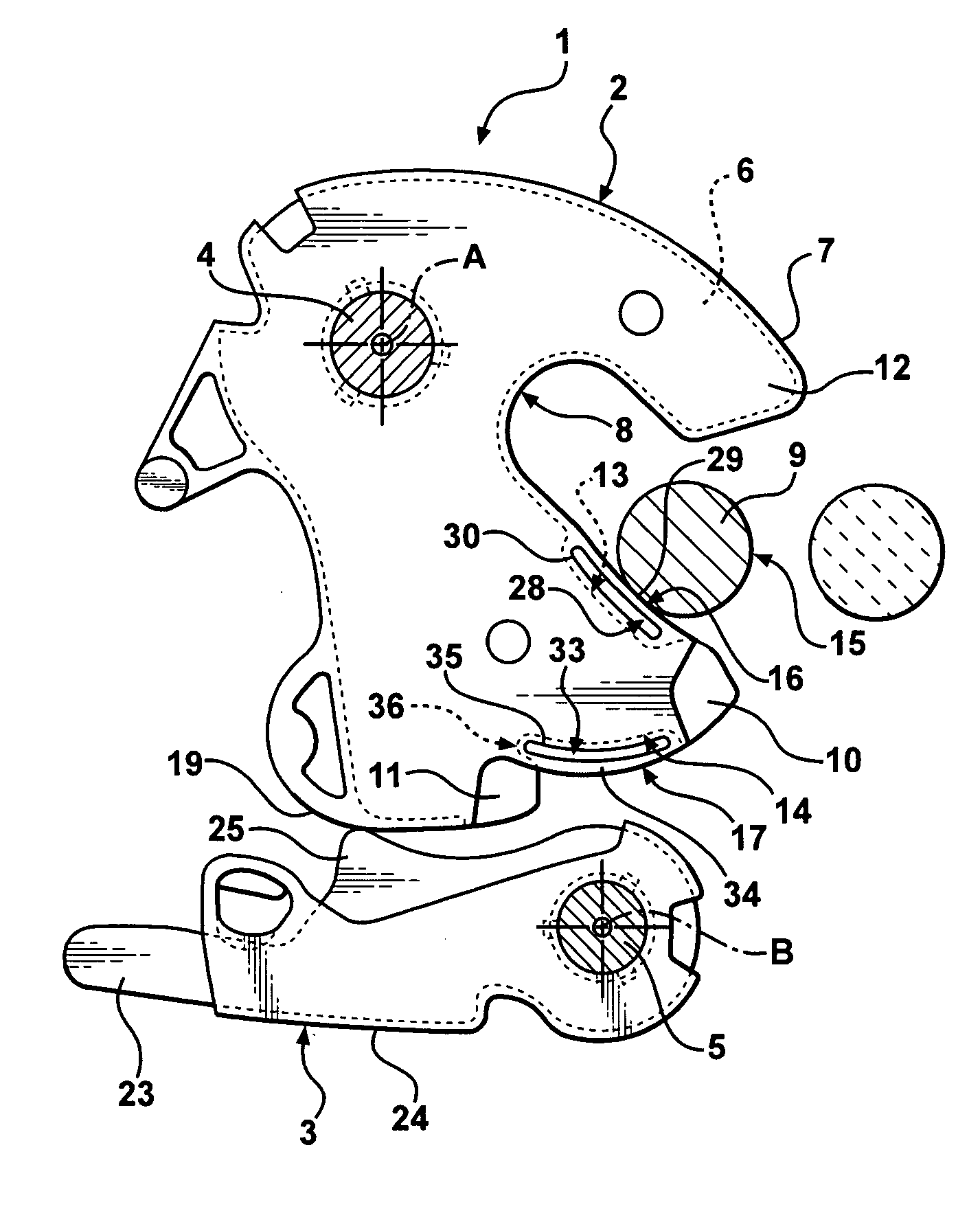
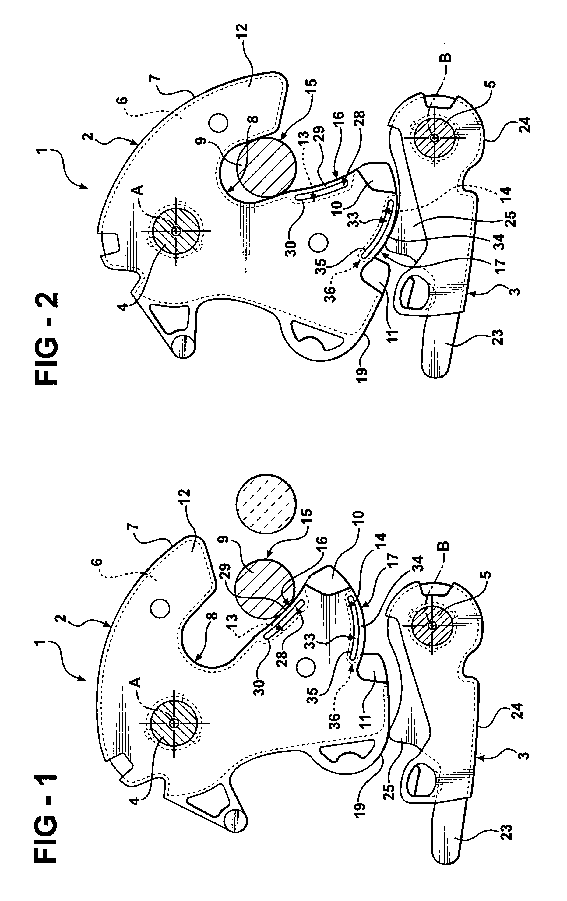
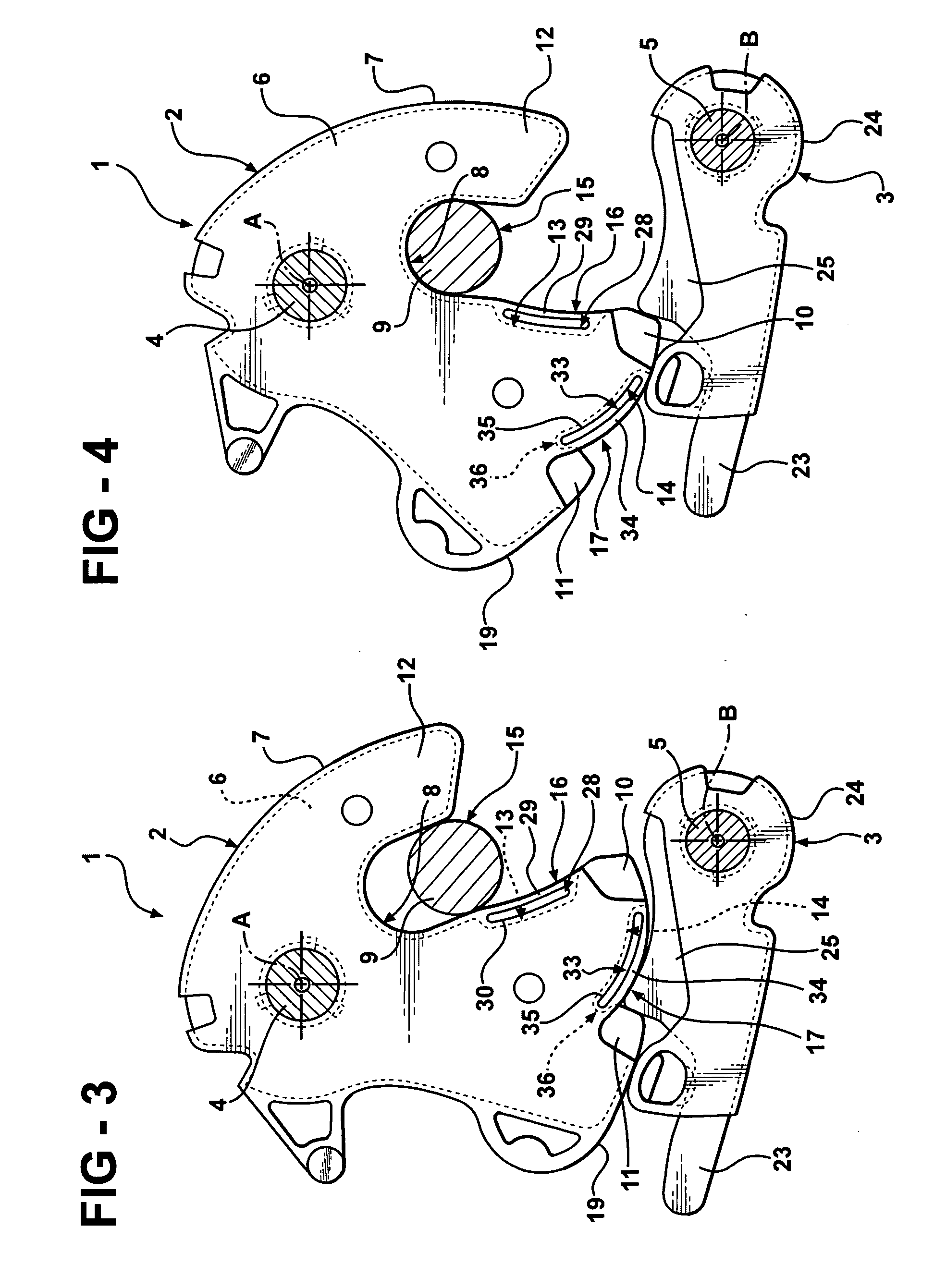
[0022] Referring to FIGS. 1 to 4, a vehicle door lock is shown at 1 for a door of an automotive vehicle. It should be appreciated that the term “door” is used in its broadest sense to indicate any member movable between an open and closed position to open and close an access opening in an internal compartment of a vehicle, and therefore, includes hoods and rear doors or lift gates, in addition to the vehicle side doors referred to herein purely by way of example.

[0023] Lock 1 substantially comprises a fork 2 and a latch 3 hinged about respective fixed pins 4, 5 having respective parallel axes A, B. More specifically, fork 2 is defined by a contoured plate 6 made of rigid material, e.g. metal, and lying in a plane perpendicular to axis A; and by a coating 7 made of relatively yielding material, e.g. plastic, and covering plate 6.

[0024] Plate 6 (shown without coating 7 in FIG. 5) comprises a C-shaped peripheral seat 8 for receiving a cylindrical portion 9 of a striker 15 (known and ...


PUM


Abstract

A vehicle door lock (1) having a fork (2) which rotates about a first axis (A) between a release position and at least one lock position engaging a fixed striker (15), and a latch (3) which rotates about a second axis (B), is loaded elastically towards the fork (2), and has a catch portion (25) which clicks onto a tooth (11) of the fork (2) to lock the fork (2) releasably in the lock position. The fork (2) is defined by a main body (6) made of rigid material, and by an outer coating (7) made of relatively yielding material and having, adjacent to the tooth (11), a slot (33) defining a peripheral edge (34) which flexes inwards of the slot (33) when struck by the catch portion (25) of the latch (3) engaging the tooth (11) of the fork (2). The main body (6) has a recess (36) close to the root of the tooth (11); and the slot (33) is at least partly superimposed over the recess (36) to allow the peripheral edge (34) to flex inwards of the slot (33) wherever the catch portion (25) of the latch (3) strikes the fork (2).

Description

FIELD OF THE INVENTION [0001] The present invention relates to a vehicle door lock for an automotive vehicle. BACKGROUND OF THE INVENTION [0002] As is known, vehicle door locks normally comprise a supporting body fixed to a door of the vehicle and a lock mechanism fitted to the supporting body and which engages a striker integral with a door post. [0003] The lock mechanism substantially comprises a fork hinged to the supporting body about a fixed first pin and loaded elastically into a release position, and a latch hinged to the supporting body about a fixed second pin and pushed elastically so that a catch portion of it clicks onto a peripheral edge of the fork. [0004] More specifically, the fork comprises a main body, normally in the form of a metal plate, which defines a C-shaped seat for engaging a normally cylindrical portion of the striker, and comprises two lateral shoulders or teeth which engage the catch portion of the latch. A first tooth is contiguous to the seat, while t...

Claims


Application Information

Patent Timeline
IPC IPC(8): E05C3/06
CPCE05B85/26E05B2015/165Y10S292/56E05B77/40E05B77/38Y10T292/1047
Inventor OTTINO, FRANCO GIOVANNIBIGAZZI, LUCA
Owner INTIER AUTOMOTIVE CLOSURES SPA CASCINE VIA
Why Eureka
Try Eureka