Hall effect sensor temperature compensator

a technology of hall effect sensor and temperature compensation, which is applied in the direction of electronic commutators, motor/generator/converter stoppers, dynamo-electric converter control, etc., can solve the problems of uncompensated hall effect sensor, high cost of hall effect sensor, and only use, and is more expensive than other types of common magnets

Inactive Publication Date: 2006-12-14
FORD GLOBAL TECH LLC
View PDF13 Cites 10 Cited by
  • Summary
  • Abstract
  • Description
  • Claims
  • Application Information

AI Technical Summary

Problems solved by technology

Compensated Hall Effect sensors, however, are more costly than uncompensated Hall Effect sensors and are only used with Samarian cobalt (“SmCo”) magnets, which are more costly than other types of common magnets, such as neodymium iron boron (“NeFeB”) magnets.

Method used


Image

  • Hall effect sensor temperature compensator
  • Hall effect sensor temperature compensator

Examples


Embodiment Construction

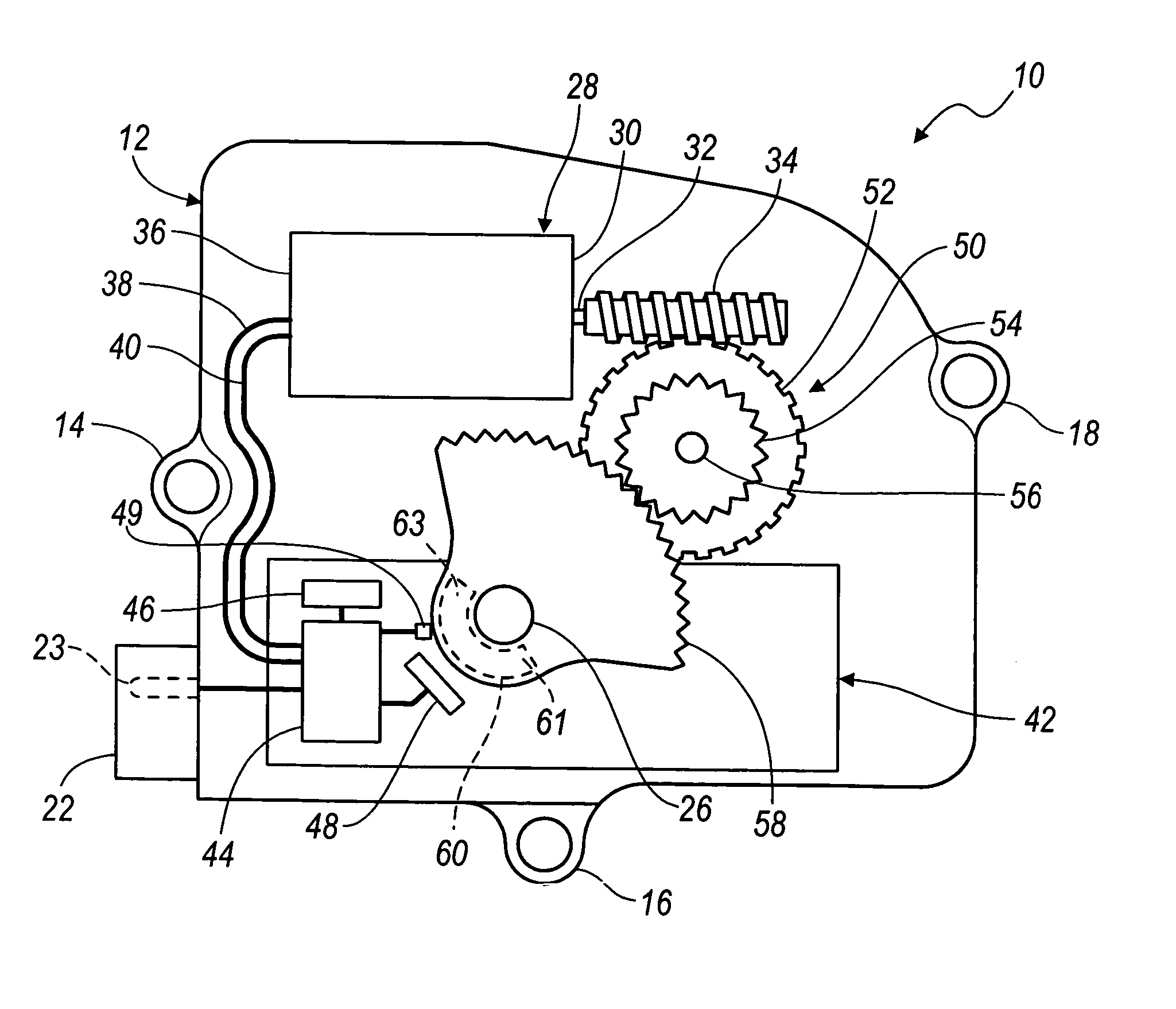
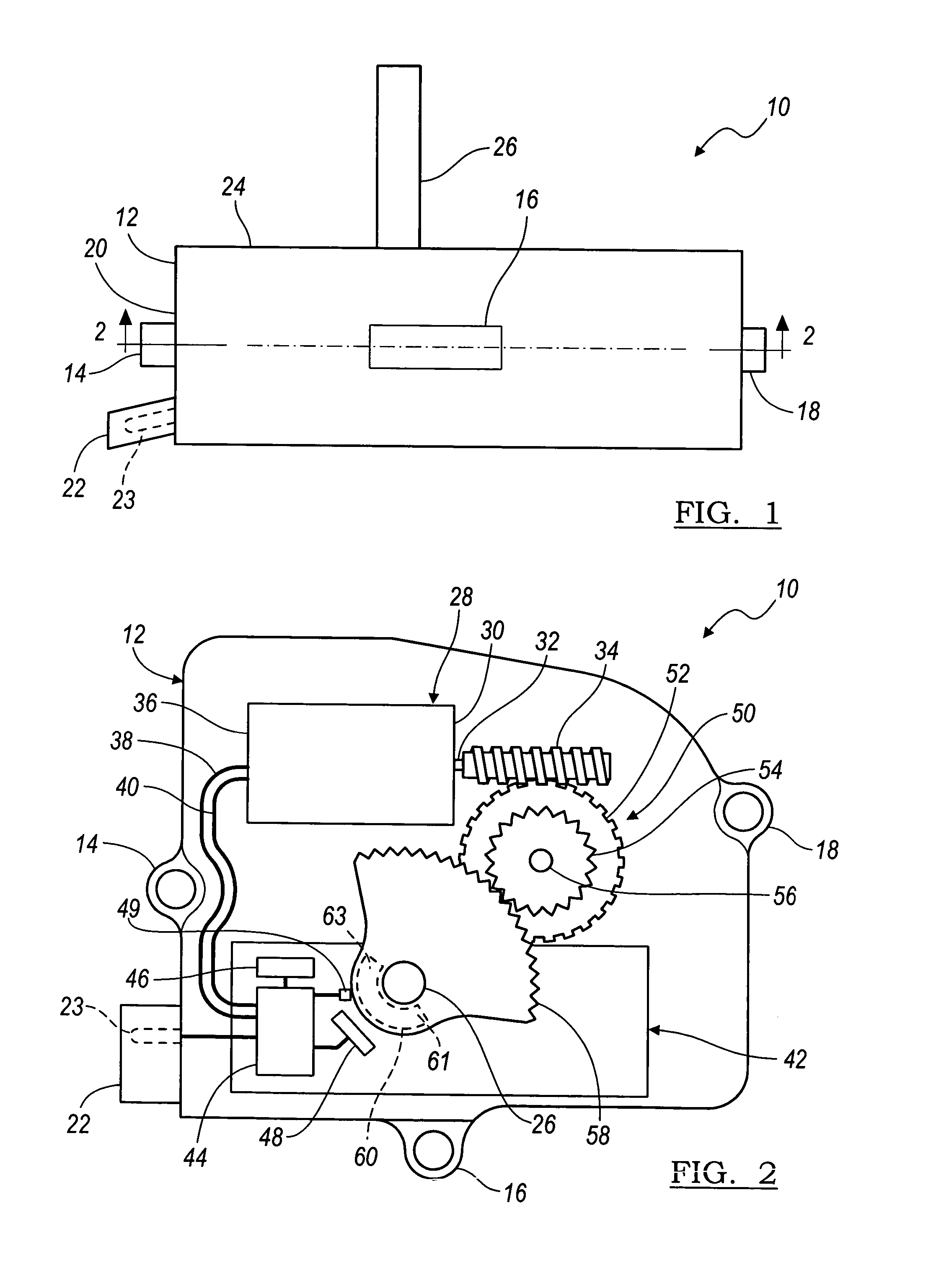
[0013] Referring to FIG. 1, an actuator 10 is illustrated therein and includes a housing 12 having mounting points 14, 16, 18. The housing is typically made of plastic but may be made of metal. Extending from a side 20 of the housing 12 is an electrical connector 22 that allows for outside communication with the actuator 10 via a pin 23. Extending from a one side 24 of the housing 12 is an output shaft 26. Generally, the output shaft 26 is made of a metal, such as steel, but may alternatively be made of plastic.

[0014] Referring now to FIG. 2, inside the housing 12 is located a motor 28, preferably an electrical motor of conventional construction. At a first end 30 of the motor 28 is an output 32 extends from one end 30 of the motor 28. Also extending from the motor 28 are motor control lines 38, 40.

[0015] In addition to the motor 28, disposed within the housing 12, is an electronic control module (ECM) 42 that is connected to the motor 28 via the control lines 38, 40. The ECM 42 i...


PUM


Abstract

A system and method for compensating the output of an uncompensated Hall Effect sensor used to monitor an output shaft of an actuator. The actuator includes an output shaft, a magnet coupled to the output shaft, a motor for rotating the output shaft between a first position and a second position and an electronic control module having a controller, a diode and an uncompensated Hall Effect sensor.

Description

BACKGROUND [0001] 1. Field of the Invention [0002] The present invention relates to electronically controlled actuators and more specifically to electronically controlled actuators having Hall Effect sensors. [0003] 2. Description of the Known Technology [0004] Automobiles are equipped with electronically controlled actuators to open and close the doors of various passageways located throughout the automobile. These passageways may include heating, ventilation, air conditioning passageways, or air passageways to the intake manifolds of internal combustion engines. These actuators will open and close the door of a passageway by rotating an output shaft connected to the door. The actuator determines if the output shaft has rotated the door to a fully opened or to a fully closed position by monitoring the output of a Hall Effect sensor configured to monitor a magnetic field created by a magnet coupled to the output shaft. This magnetic field will vary with the position of the output sh...

Claims


Application Information

Patent Timeline
Patent Type & Authority Applications(United States)
IPC IPC(8): H02P1/04
CPCH02P6/16
Inventor RUTKOWSKI, DAVID J.FLOROS, JOHN H.SHARAA, IMAD
Owner FORD GLOBAL TECH LLC
Why Eureka
Try Eureka