Method and apparatus for RF signal demodulation

a signal demodulation and signal technology, applied in the field of rf reception, can solve the problems that the simple zif design cannot be adopted in situations requiring it, and achieve the effect of reducing the number of zifs

Inactive Publication Date: 2006-12-14
AIROHA TECHNOLOGY CORPORATION
View PDF4 Cites 15 Cited by
  • Summary
  • Abstract
  • Description
  • Claims
  • Application Information

AI Technical Summary

Problems solved by technology

The first BPF 103 and second BPF 106, however, are costly to implement due to high quality and high accuracy requirements, therefore conventional filters are implemented externally.
The ZIF design, while simple, cannot be adopted for situations requiring IF signals.

Method used


Image

  • Method and apparatus for RF signal demodulation
  • Method and apparatus for RF signal demodulation
  • Method and apparatus for RF signal demodulation

Examples


Embodiment Construction

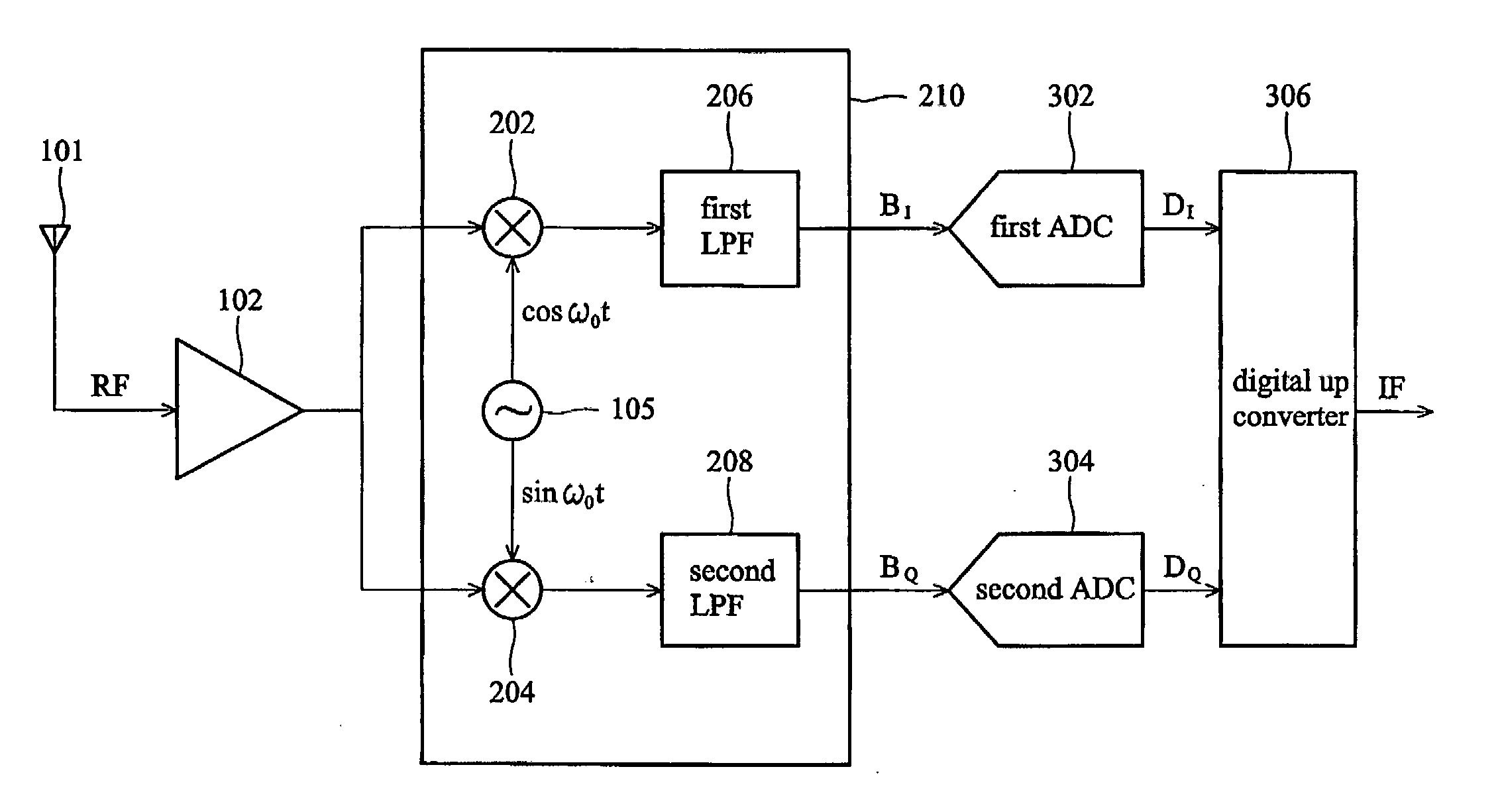
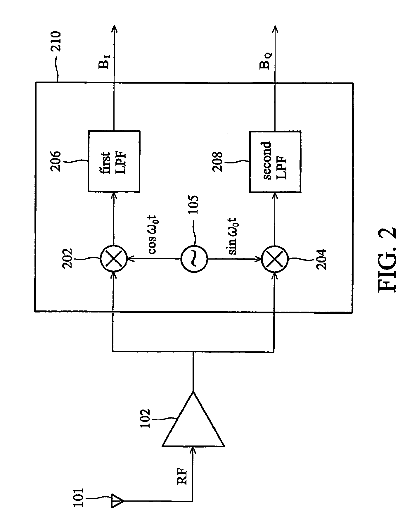
[0015]FIGS. 3a and 3b show embodiments of the RF receiver according to the invention. In FIG. 3a, the antenna 101, LNA 102 and direct conversion unit 210 are identical to the ZIF receiver in FIG. 2. In-phase baseband signal BI and quadrature baseband signal BQ are generated from the direct conversion unit 210, and then digitized by the first ADC 302 and second ADC 304 to generate corresponding in-phase digital signal DI and quadrature digital signal DQ. Thereafter, a digital up converter 306 combines the in-phase digital signal DI and quadrature digital signal DQ into the IF signal. The embodiment is based on conventional ZIF architecture, thus possesses good image rejection capability. A detailed description of the digital up converter 306 is disclosed in FIG. 4 and FIG. 5.

[0016] In FIG. 3b, the direct conversion unit 220 differs from the direct conversion unit 210 in FIG. 3a, in that local OSC 105 provides an oscillation frequency different from the RF carrier frequency. For exam...


PUM


Abstract

A radio frequency (RF) receiver is provided, comprising an antenna, a low noise amplifier, a down converter, a first analog to digital converter (ADC), a second ADC, a digital up converter. The antenna receives an RF signal, and the LNA coupled to the antenna amplifies the RF signal. The down converter, coupled to the LNA, down converts the RF signal to generate an in-phase baseband signal and a quadrature baseband signal. The first ADC, coupled to the down converter, digitizes the in-phase baseband signal to an in-phase digital signal. The second ADC, coupled to the down converter, digitizes the quadrature baseband signal to a quadrature digital signal. The digital up converter, coupled to the first and second ADCs, up converts the in-phase digital signal and quadrature digital signal to generate an intermediate frequency (IF) signal.

Description

BACKGROUND [0001] The invention relates to RF reception, and in particular, to a method for generating an IF signal from an RF signal. [0002]FIG. 1 shows a conventional super heterodyne receiver. An antenna 101 receives a radio frequency (RF) signal. A low noise amplifier (LNA) 102 amplifies the RF signal, and a first band pass filter (BPF) 103 filters the RF signal to eliminate unnecessary components therein. A mixer 104 converts the frequency of the RF signal based on an oscillation frequency generated from a local oscillator (OSC) 105 to generate an intermediate frequency (IF) signal comprising image components. A second BPF 106 filters the IF signal to eliminate unnecessary image components and outputs a pure IF signal. The oscillation frequency generated by the local OSC 105 determines the frequency of the IF signal. The super heterodyne architecture is compact, providing excellent channel selection capability, while avoiding adjacent band signal interference. The first BPF 103...

Claims


Application Information

Patent Timeline
Patent Type & Authority Applications(United States)
IPC IPC(8): H03M1/12
CPCH04B1/0028H04B1/28H04B1/0032
Inventor WANG, CHUNG-CHENGYANG, JOHN-SAN
Owner AIROHA TECHNOLOGY CORPORATION
Why Eureka
Try Eureka