
Display panel with camera function

Inactive Publication Date: 2006-12-14
YANG SHOU AN +1
View PDF2 Cites 59 Cited by
  • Summary
  • Abstract
  • Description
  • Claims
  • Application Information

AI Technical Summary

Benefits of technology

[0009] The primary purpose of the present invention is to provide a display panel with camera function to facilitate assembly of a camera module, lower production cost, maintain resources of the main unit, present better view of the appearance of the display panel, and allow more diversified design of the appearance of the product.
[0010] To achieve the purpose, the present invention includes a camera module built in an extension area of a surface plate of the display panel; and the circuit of the camera module is integrated with a circuit of a display module; and the signals are transmitted through a single signal transmission unit. The present invention provides the following advantages:

Problems solved by technology

Accordingly, an extra workstation is required in the process of the assembly of the digital camera to result in increased work hours and production costs; and the signal transmission unit of the digital camera module would have to occupy the connection port otherwise reserved for the circuit board of the main unit thus to reduce the mechanism of the main unit to enjoy externally connected expansion of resources.
Furthermore, the digital camera module has to be squeezed into a limited space of the casing of the product to cause additional limitation to the design of the finished product while leaving a significant protrusion to its appearance to damage the aesthetic aspect of the finished product.
However, up to now, the attempt of having the camera module mounted in the surface plate of the display panel has not yet been seen.
Quite obviously, the prior art of having the camera module mounted to the frame (or casing) of the display panel brings many flaws to the manufacturers of products adapted with the display panel including difficult assembly, increased production costs, taking too much resources of the main unit, and limited design for the appearance to deliver shattered visual impression to its user.

Method used


Image

  • Display panel with camera function
  • Display panel with camera function
  • Display panel with camera function

Examples


Embodiment Construction

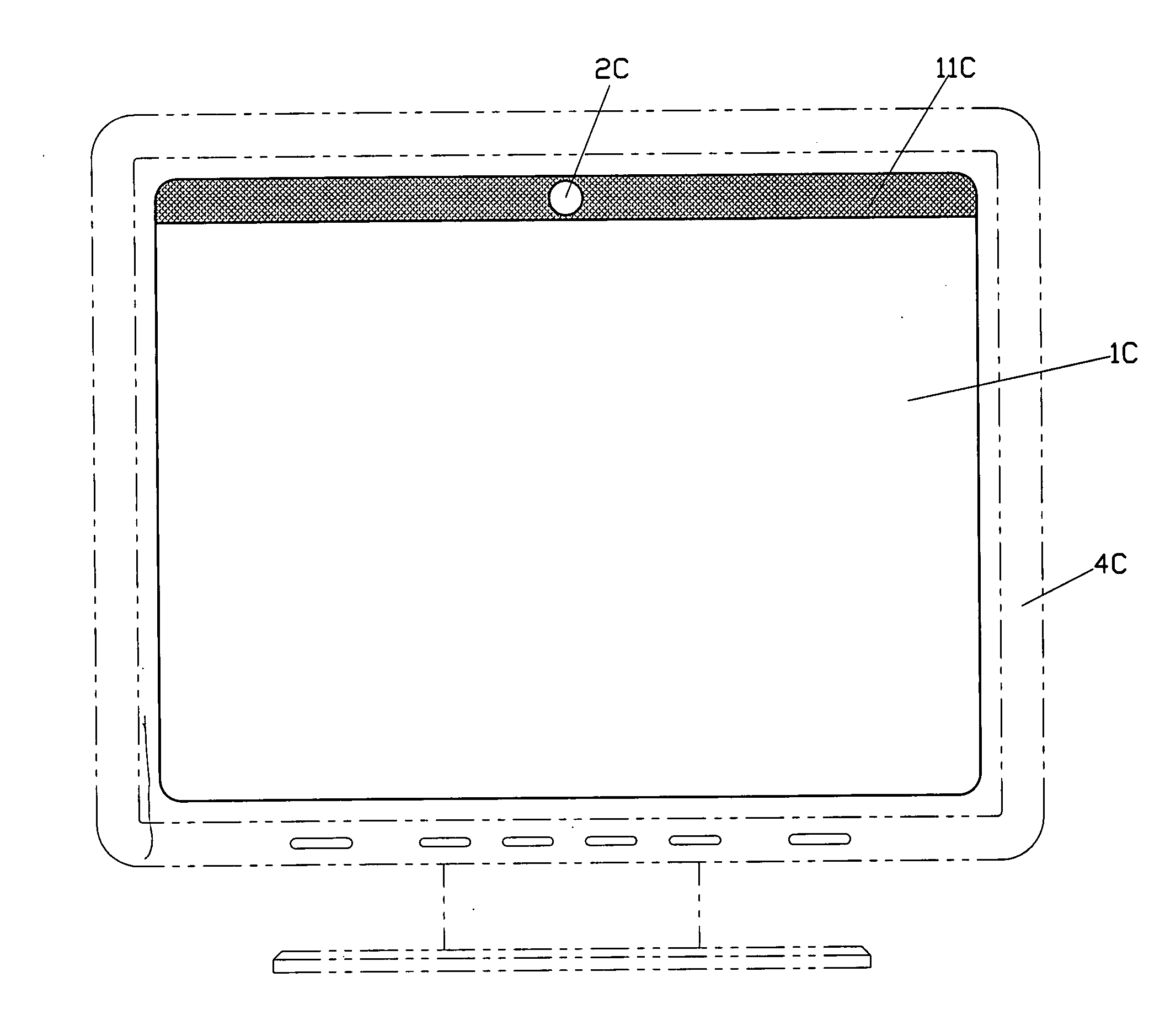
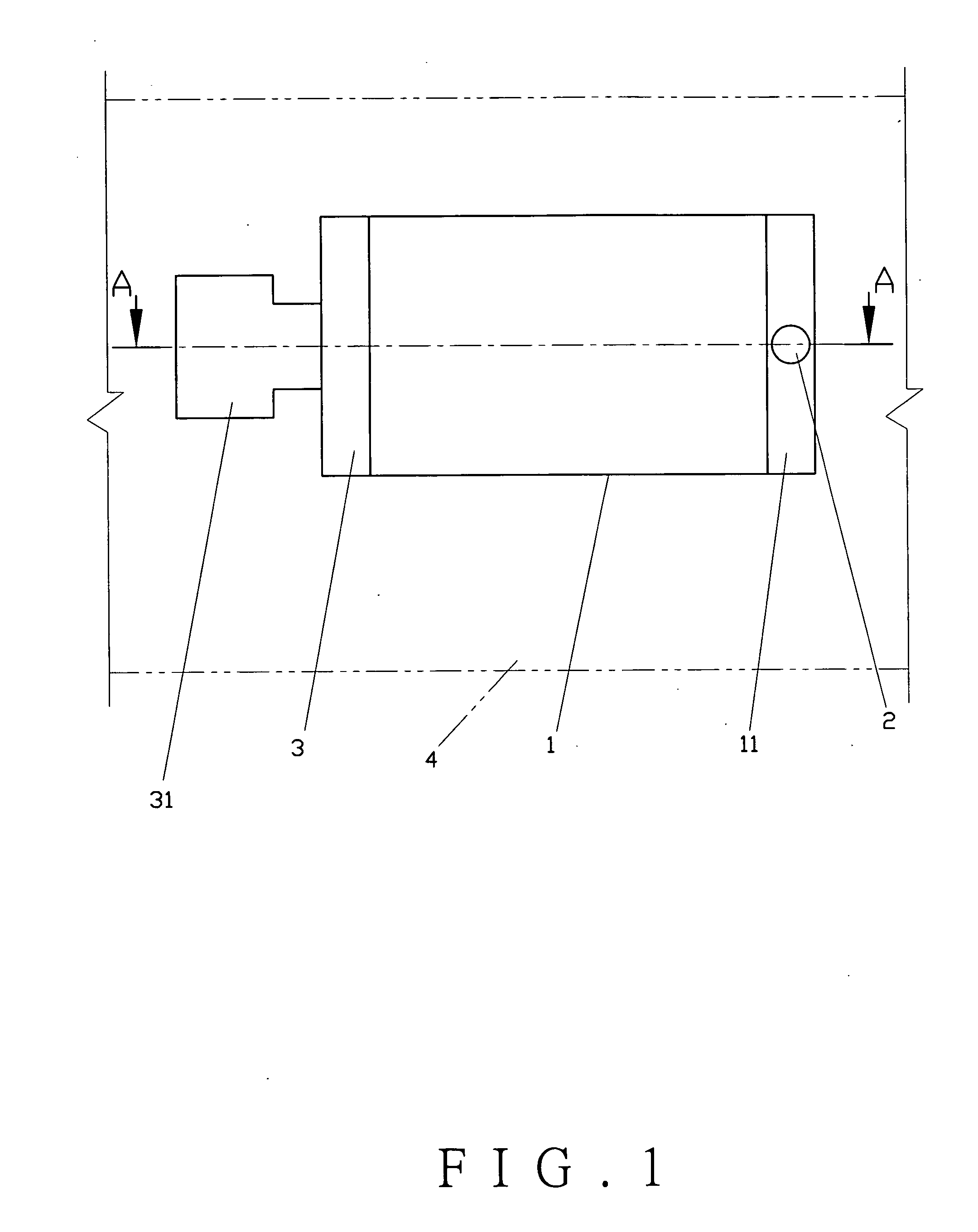
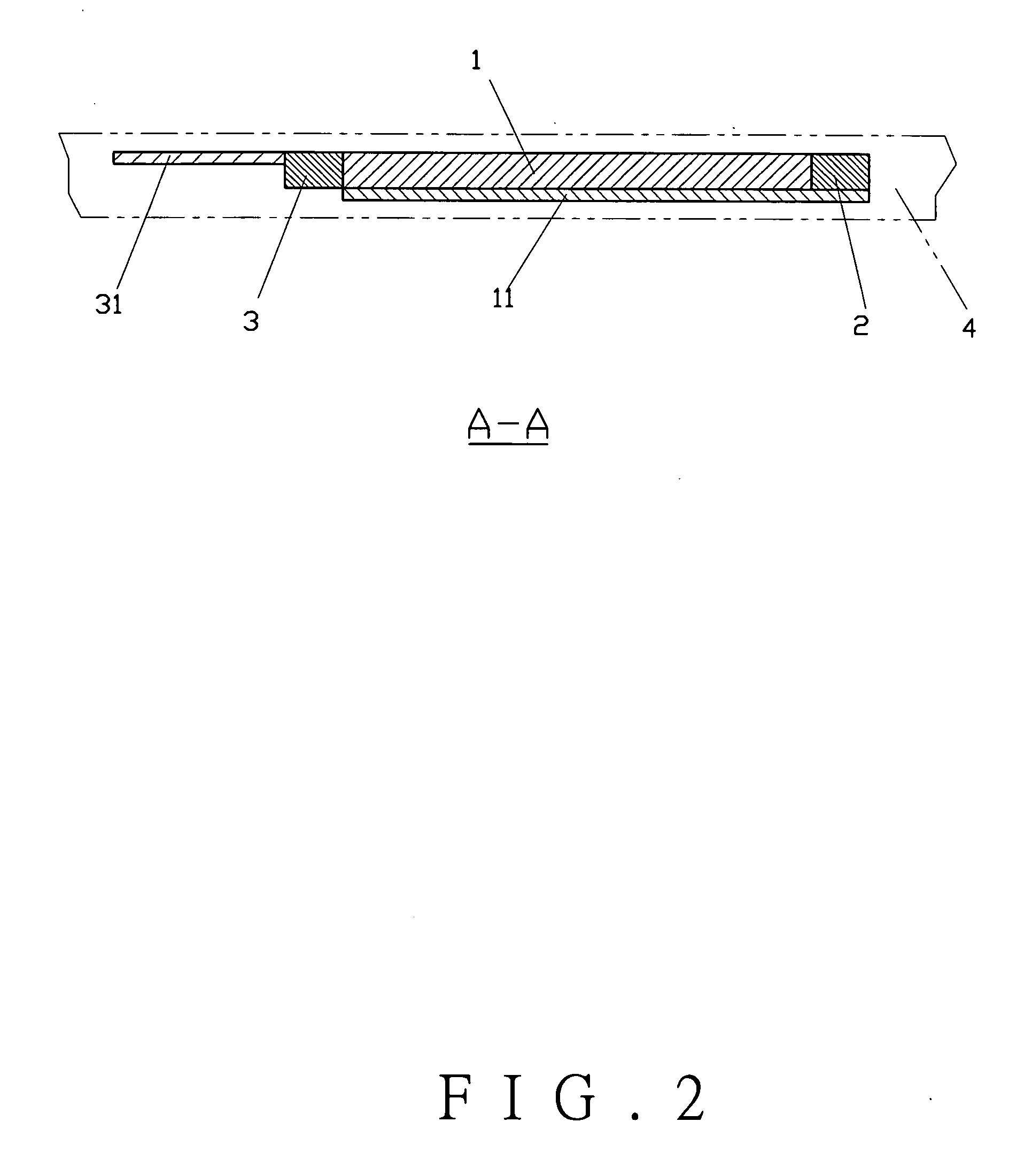
[0021] Referring to FIGS. 1 and 2, an extension area (11) is provided to a surface plate of a display panel (1) and a camera module (2) is built in the extension area (11). The circuit of the camera module (2) is integrated with a circuit of a display module into a circuit board (3) and signals are transmitted through a single signal transmission unit (31). All the components described above are installed on a support member (4). The support member (4) may be a frame or a casing of a finished product for the present invention to become a module. The surface of the extension area (11) is coated leaving only a lens area to permit the light. Accordingly, as the visual impression is concerned, the installation of a camera lens can hardly be observed to allow better visual impression to the user since only the display area is in vision. As for the manufacturer of the finished product adapted with the display panel, the present invention allows easier assembly of the camera module and div...


PUM


Abstract

A display panel with camera function has a camera module built in an extension area of a surface plate of the display panel. The circuit of the camera module is integrated with a circuit of a display module, and signals are transmitted through a single signal transmission unit. The appearance of the display panel facilitates diversified design to allow easier assembly of the camera module and much better sense of vision.

Description

BACKGROUND OF THE INVENTION [0001] (a) Field of the Invention [0002] The present invention relates to a display panel with camera function, and more particularly a display panel having a camera module built in an extension area of a surface plate of the display panel. The circuit of the camera module is integrated with a circuit of a display module, and signals are transmitted through a single signal transmission unit. [0003] (b) Description of the Prior Art [0004] Whereas most of the 3C products generally available in the market feature that a single product is integrated with multiple functions, the cellular phone incorporated with digital camera is the best example. Wherein, a digital camera lens is mounted onto the casing of the cellular phone. Furthermore, to facilitate the PC user to conduct digital conference via Internet, a digital camera lens is mounted to the frame of a liquid crystal display (LCD). [0005] In those products described above, they are adapted with the digita...

Claims


Application Information

Patent Timeline
IPC IPC(8): H04N5/222
CPCH04M1/0264H04N5/2251H04M2250/52H04M1/0266H04N23/50
Inventor YANG, SHOU-ANYANG CHEN, HSIANG-YUAN
Owner YANG SHOU AN
Learn More