
Electrothermal inlet ice protection system

a technology of inlet guide vane and electric inlet air, which is applied in the direction of machines/engines, mechanical equipment, liquid fuel engines, etc., can solve the problems of not only tapped into engine performance, but also severely limited capability in organic matrix composite applications, and the inability to flow the required volume of air to the inlet guide vane,

Active Publication Date: 2006-12-14
RAYTHEON TECH CORP
View PDF38 Cites 18 Cited by
  • Summary
  • Abstract
  • Description
  • Claims
  • Application Information

AI Technical Summary

Problems solved by technology

This system not only taps into engine performance, but also has severely limited capability in organic matrix composite applications.
Current organic matrix composite materials capable of producing fan inlet cases are limited to maximum use temperatures of 350° F. Compressor discharge air can be significantly hotter than this limit, depending on engine speed.
At ground idle, where the compressor discharge air temperature is relatively low (in icing conditions), flowing the required volume of air to anti-ice an inlet guide vane is not possible because of the limitations of the tortuous path within the inlet case manifold, struts, plumbing and valves.
This, however, has not produced satisfactory results in all cases.
Metallic inlet cases also have limitations.
Erosion coatings, necessary in certain applications, have maximum use temperature limits of 450° F. Deicing can occur for more of the specified range, but the cost in performance and weight is still prohibitive.

Method used


Image

  • Electrothermal inlet ice protection system
  • Electrothermal inlet ice protection system
  • Electrothermal inlet ice protection system

Examples


Embodiment Construction

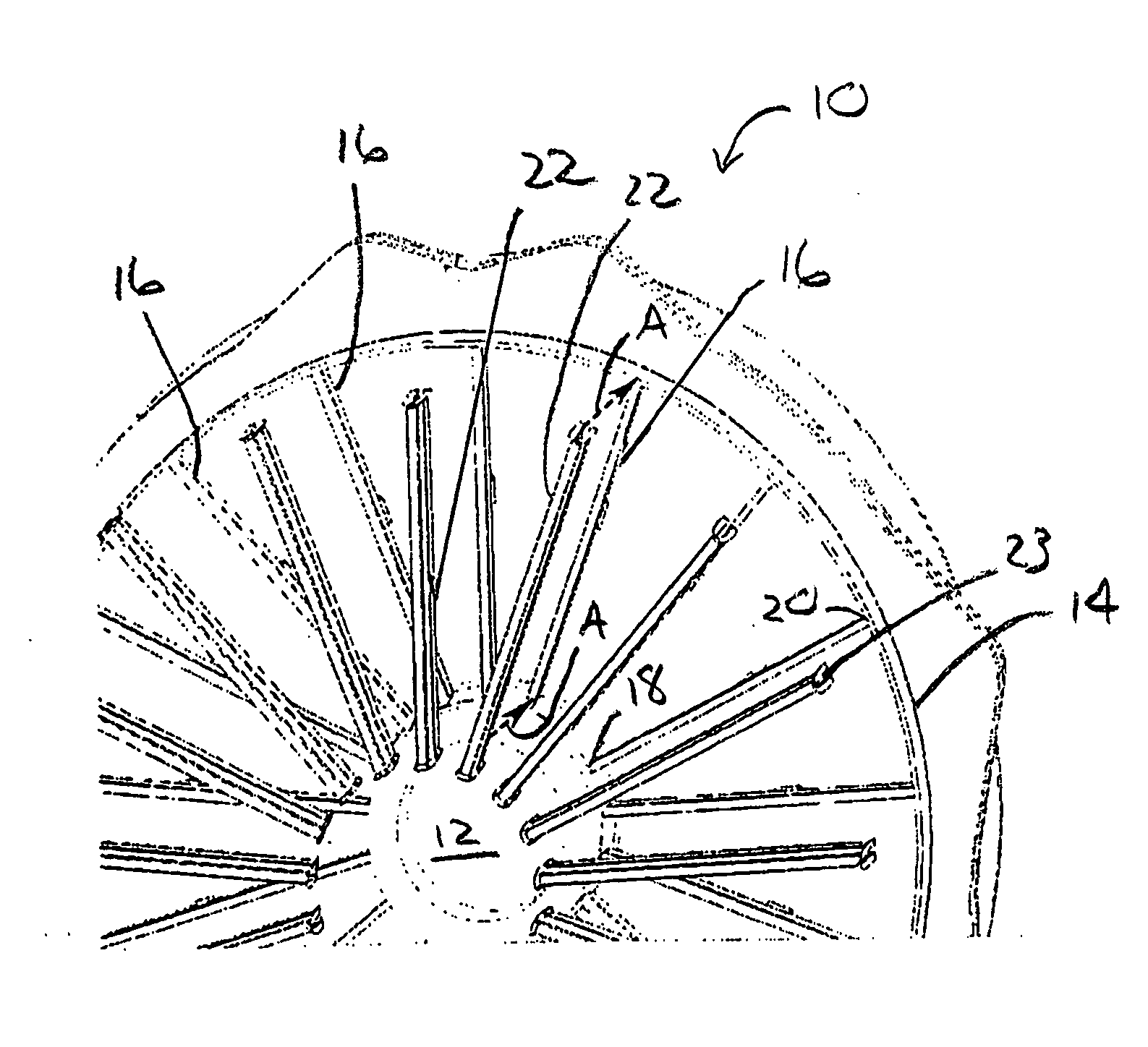
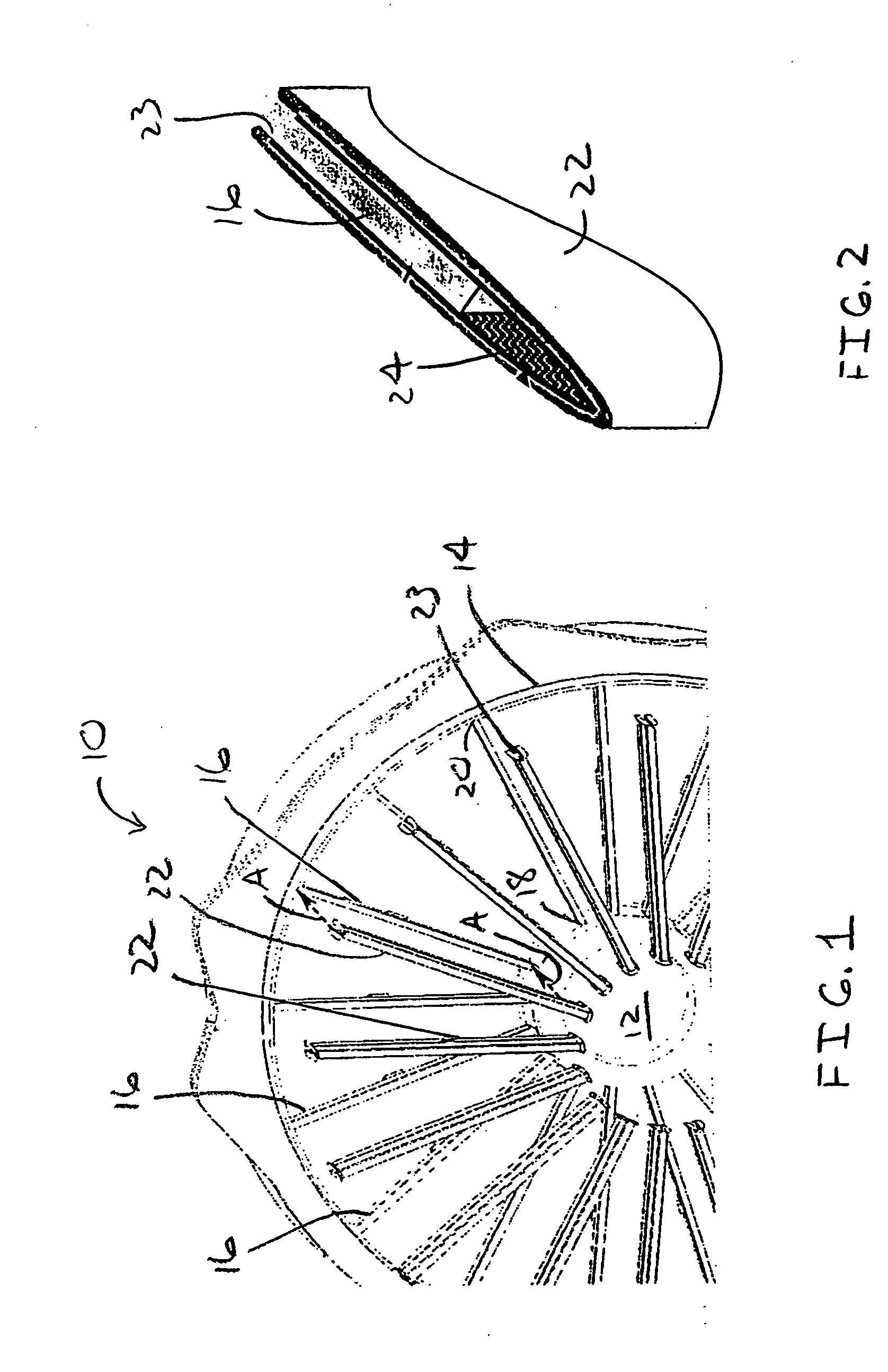
[0011] With reference to FIGS. 1 and 2, a modular fan inlet ice protection system embodying the present invention is generally indicated by the reference number 10. The system 10 provides a reliable, low cost means to anti / deice an engine fan inlet case and inlet guide vanes that is better suited for use with organic matrix composite materials than with conventional bleed air systems.

[0012] The system 10 comprises a center ring 12, an outer ring 14 and a plurality of struts 16 each preferably fabricated at least in part from an organic matrix composite. The struts 16 are each coupled at a first end 18 to the center ring and at a second end 20 to the outer ring to thereby form a structural ring-strut-ring inlet case component.

[0013] A structural ring-strut-ring inlet case component, housing a bearing compartment, a forward engine attachment to an airframe, and attachment of fan inlet guide vanes is manufactured using low cost lightweight methods such as, for example, organic matrix...


PUM


Abstract

A modular fan inlet ice protection system includes a center ring, an outer ring and a plurality of struts. The struts are each coupled at a first end to the center ring, and at a second end to the outer ring. A plurality of shell members are each configured to be removably coupled to a corresponding strut. Moreover, the shell members each include an electrothermal heater element Preferably the system further includes a plurality of inlet guide vanes each including an electrothermal heater element.

Description

FIELD OF THE INVENTION [0001] This invention relates generally to deicing systems for aircraft engines, and more particularly to an electrothermal inlet ice protection system. BACKGROUND OF THE INVENTION [0002] Fan module components are protected from ice accretion using hot air bled from the high compressor. Hot air is supplied via a manifold into hollow cavities in the fan inlet case struts, thereby heating the struts and nose cone. Ultimately, this air is channeled through a series of ultrasonically drilled holes (approximately 200 per strut) to produce a hot air film on the pressure side of an inlet guide vane. This system not only taps into engine performance, but also has severely limited capability in organic matrix composite applications. [0003] Current organic matrix composite materials capable of producing fan inlet cases are limited to maximum use temperatures of 350° F. Compressor discharge air can be significantly hotter than this limit, depending on engine speed. At gr...

Claims


Application Information

Patent Timeline
IPC IPC(8): F04D29/00
CPCF01D25/02F05D2300/603Y02T50/672F02C7/047Y02T50/60
Inventor EUVINO, FRANK J. JR.VINCIQUERRA, ANTHONY J.
Owner RAYTHEON TECH CORP
Learn More