Unlock instant, AI-driven research and patent intelligence for your innovation.

Nasogastric tube introducer device

a technology of introducer device and stomach tube, which is applied in the direction of feeding tube, ear treatment, catheter, etc., can solve the problems of severe sore throat, difficult insertion of stomach tube, and injury of oral mucosa (lining)

Inactive Publication Date: 2006-12-14
ABDELATTI MOHAMED OSMAN
View PDF6 Cites 2 Cited by
  • Summary
  • Abstract
  • Description
  • Claims
  • Application Information

AI Technical Summary

Benefits of technology

[0046] According to another aspect of the present invention there is provided a nasogastric tube introducer device for assisting the insertion of a nasogastric tube into the stomach of an anaesthetised patient is comprised of a curved hollow tube with two extensions at its proximal end and a hair-line slit extending from its proximal end to its distal end such that the slit in the wall of the tube is partially closed by a film of glue along half of the inner depth of the slit and the remaining outer half of the slit is left open to help mark the position of the slit.

Problems solved by technology

A further aim of the NGT is to empty the stomach of air / anaesthetic gases because a distended stomach may be damaged during blind insertion of equipments essential for laparoscopic (keyhole) surgery e.g. removal of the gall bladder.
However, in practice, the presence of a tracheal tube in the oral cavity makes the insertion of the pliable NGT (stomach tube) difficult because the latter tends to curl in the mouth instead of passing into the stomach.
This repeated grasping of the tube to advance it in the stomach leads to injury of the oral mucosa (lining) and severe sore throat after the operation.
One disadvantage is the fact that time is wasted in preparing and cutting the tracheal tube to adjust its length and to create a slit along its side.
Another disadvantage is the fact that the modified tracheal tube also has no means for holding it outside the mouth and can easily be lost into the oesophagus.
A further disadvantage is the fact that the manufactures of tracheal tubes may deny responsibility for any damage / complications caused by modification of their tracheal tubes and their use for a different purpose than what they are intended for i.e. for ventilation and not as guide to the NGT.

Method used


Image

  • Nasogastric tube introducer device
  • Nasogastric tube introducer device

Examples


Embodiment Construction

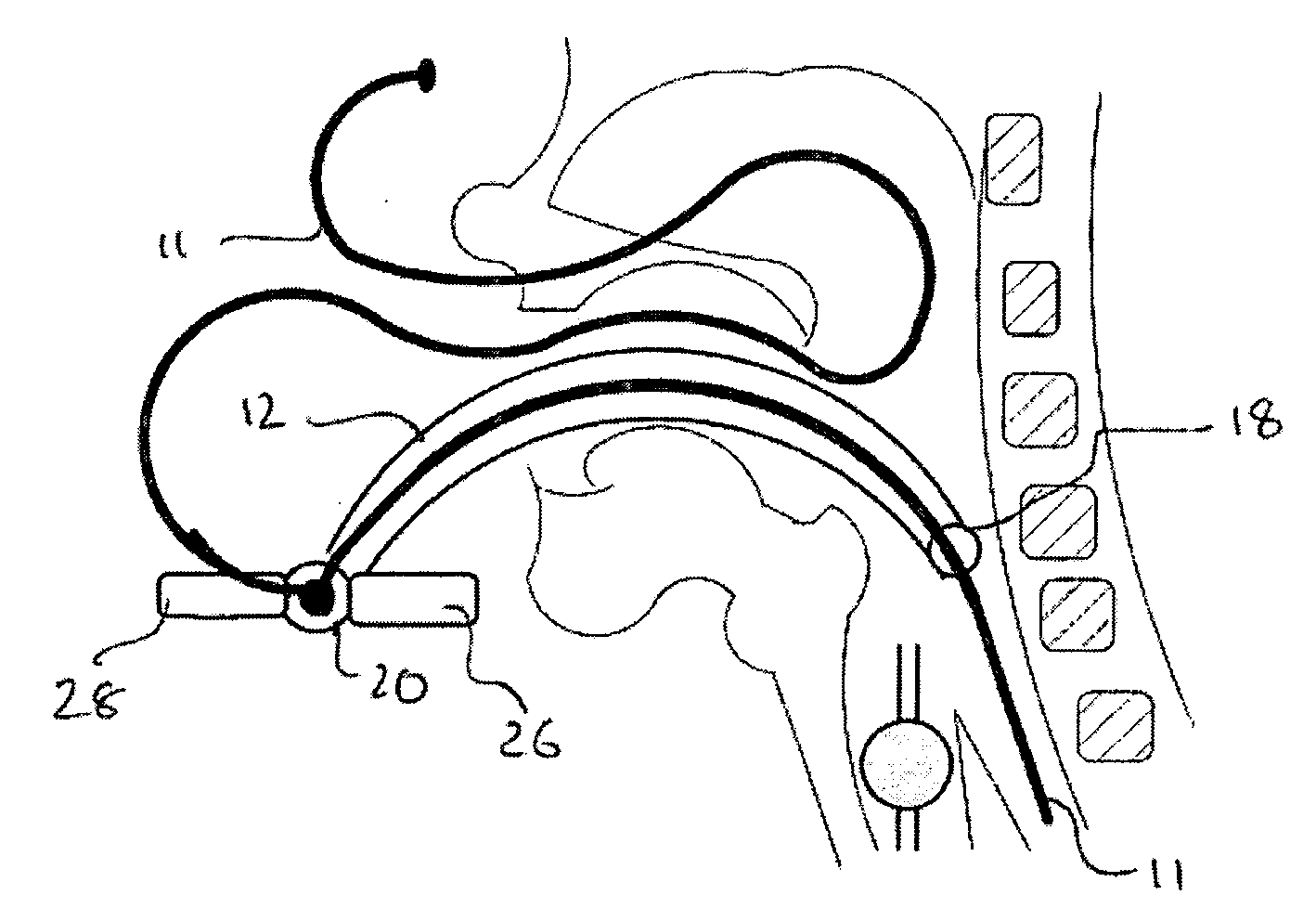
[0052] The nasogastric tube (NGT) introducer device 10 comprises a conduit 12 providing a passageway 16 therethrough. The conduit comprises an elongate tube which extends longitudinally from a first longitudinal end 20 (the proximal end) to a second longitudinal end 18 (the distal end) or tip. In use, the conduit 12 is inserted into the mouth of a patient in order for the proximal end 20 to locate outside the mouth of the patient and for the distal end 18 to locate in or towards the oesophagus of the patient. The NGT 11 can then be easily inserted into the passageway 16 of the proximal end 20 of the conduit 12 and the NGT is easily guided down into the oesophagus of the patient.

[0053] The conduit 12 comprises a longitudinal releasing portion in the form of a separable portion 14 extending longitudinally along the conduit 12. The separable portion 14 enables the periphery of the conduit to be separated in order to define a slit along the longitudinal length of the peripheral wall of...


PUM


Abstract

A device for introducing a nasogastric tube in the stomach of anaesthetised or comatose patients by medical personnel is described. It consists of a curve-shaped plastic or rubber tube. It has two extensions 2, 3 at its proximal end 4 for holding it and to prevent it from being dislodged into the oesophagus during insertion of the NGT and a hair-line slit 5 along its side extending from its proximal end 4 to the distal end 6 for separating it from the nasogastric tube. The depth of the slit in the wall of the introducer is partially glued to prevent the tip of the nasogastric from leaving the introducer via the slit during insertion while allowing the nasogastric tube to be easily peeled off the introducer.

Description

FIELD OF THE INVENTION [0001] This invention relates to a device to assist anaesthetists with insertion of a nasogastric tube (NGT) in the stomach of an anaesthetised or comatose patient. BACKGROUND TO THE INVENTION [0002] The insertion of a nasogastric (stomach) tube (NGT) is an important procedure that is routinely performed in the daily practice of anaesthesia for emergency and elective abdominal surgical operations. All ventilated patients in the intensive care unit have a nasogastric tube placed for therapeutic, diagnostic and or feeding. The NGT is a narrow—bore soft plastic / rubber tube. It is usually inserted via the nose into the mouth and then it is advanced, blindly, so that its tip lies in the stomach. One aim of the NGT is to empty the stomach of secretion and prevent abdominal distension in intestinal obstruction. Another aim of the NGT is to instil drugs or feeding material into the stomach. A further aim of the NGT is to empty the stomach of air / anaesthetic gases beca...

Claims


Application Information

Patent Timeline
IPC IPC(8): A61F11/00
CPCA61M16/0461A61J15/0023A61J15/0003A61M25/0662A61M16/0415A61M16/0429
Inventor ABDELATTI, MOHAMED OSMAN
Owner ABDELATTI MOHAMED OSMAN