
Protective device for a suture

a protective device and suture technology, applied in the field of suture protection devices, can solve the problems of suture knots that stand up, become unknotted, and various potential problems, and achieve the effect of reducing the risk of knot snagging

Inactive Publication Date: 2006-12-14
ANGIODYNAMICS INC
View PDF28 Cites 30 Cited by
  • Summary
  • Abstract
  • Description
  • Claims
  • Application Information

AI Technical Summary

Benefits of technology

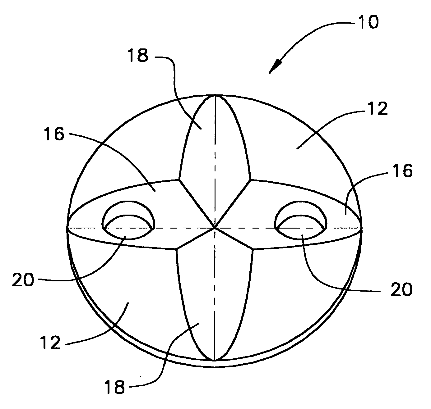
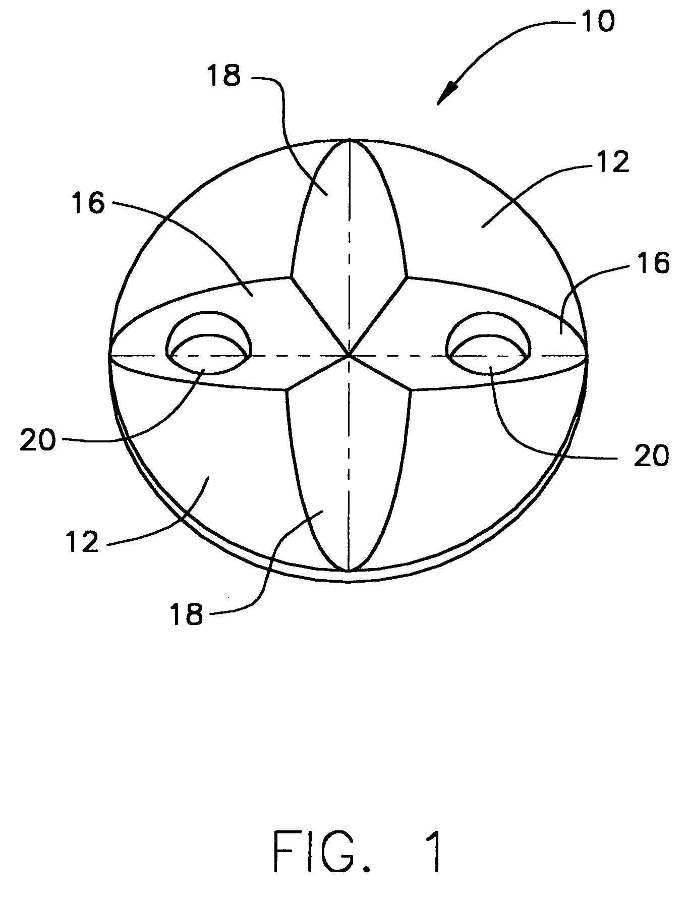
[0011] In brief, a preferred embodiment involves a small disc having first and second grooves along substantially perpendicular diameters on the top surface of the protective device. In a first one of the grooves, there are two openings through the disc to permit suture thread to be passed through and tied along the top of the disc. When tied, the suture thread and the suture knot sit in that first groove. This reduces the extent to which the suture knot is subject to abrading forces that rub across the suture. It also reduces the risk of the knot snagging when clothing is put on over the suture.
[0013] The upper surface of the disc is domed to provide a smoother profile that together with the recessed knot provides less discomfort for the wearer in pulling clothing over the bandaged disc and suture.

Problems solved by technology

When a suture is made on a patient's skin, various potential problems may occur.
However, the suture knot stands up from the disc and may be abraded and sometimes can become unknotted.
This risks having the knot suture abraded and possibly untied.
This technique of putting a blade under the fairly tightly tied knot pulls on the patient and requires care on the part of medical personnel.

Method used


Image

  • Protective device for a suture
  • Protective device for a suture
  • Protective device for a suture

Examples


Embodiment Construction

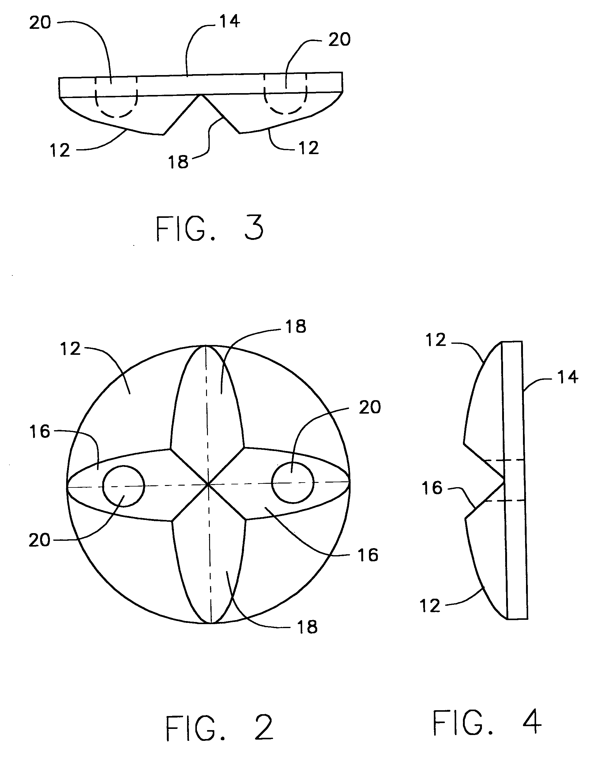
[0022] The preferred embodiment, as shown in FIGS. 1 through 4, is a disc-like protective device 10 having a domed upper surface 12 and a flat lower surface 14.

[0023] A first diametric groove 16 extends across the domed upper surface 12.

[0024] A second diametric groove 18 is perpendicular to the first groove 16 and extends across the domed upper surface 12.

[0025] Two openings 20 are located in the first groove 16 on either side of the intersection of the two grooves 16 and 18. These openings extend through the disc 10. These openings 20 allow a suture to pass through the openings 20 so that the suture can be tied into a knot.

[0026] The suture and, most importantly, the knot are recessed within the first groove 16 below the domed upper surface 12 thereby protecting the knot from abrasion and unknotting.

[0027] Recess of the suture knot into the groove 16 also provides a smooth profile in use so as to minimize snagging on clothing during donning of clothing or during patient movem...


PUM


Abstract

A disc for holding a medical suture on a patient's skin is modified by providing first and second orthogonal grooves in a domed upper surface. Through openings in one of the grooves permits the suture to be tied within that groove so that the suture has a knot contained within the groove and thus below the domed upper surface. The second groove, preferably orthogonal to the first groove, permits a scalpel to be readily inserted along the second groove to traverse the first groove and cut the suture when the suture is to be removed.

Description

BACKGROUND OF THE INVENTION [0001] This invention relates in general to a device to be used in connection with the suturing of a patient. The device serves the purpose of protecting the skin of the patient and maintaining the integrity of the suture. [0002] When a suture is made on a patient's skin, various potential problems may occur. The suture may be partially incorporated into the skin as the skin heals. The tying of the suture provides a small force over a very small area creating substantial pressure between the suture and the patient's skin. It is known to use a small button like disc to hold the suture on the patient's skin to overcome these problems. [0003] However, the suture knot stands up from the disc and may be abraded and sometimes can become unknotted. When the suture is to be removed, medical personnel have to be pick the suture off the disc to cut the suture with a scalpel. [0004] It is known to use a small disc such as a button with two openings that extend throu...

Claims


Application Information

Patent Timeline
Patent Type & Authority Applications(United States)
IPC IPC(8): A61B17/04
CPCA61B17/0401A61B2017/0414A61B2017/0404
Inventor PERCHIK, JOEL E.
Owner ANGIODYNAMICS INC
Learn More