
Rocker-arm igniter

a technology of rocker-arm and igniter, which is applied in the direction of mechanical fuzes, weapons, ammunition fuzes, etc., can solve the problems of severe injury to users, inability to properly hold irritation grenades, and user inadvertently to hold the rocker arm securely, so as to increase the safety of the rocker-arm igniter

Inactive Publication Date: 2006-12-21
NICO PYROTECHNIK HANNS JUERGEN DIEDRICHS GMBH & CO KG
View PDF24 Cites 5 Cited by
  • Summary
  • Abstract
  • Description
  • Claims
  • Application Information

AI Technical Summary

Benefits of technology

[0010] It is a principal object of the present invention to increase the safety of a rocker-arm igniter and to provide a design in which inadvertent arming of the rocker-arm igniter is practically impossible.
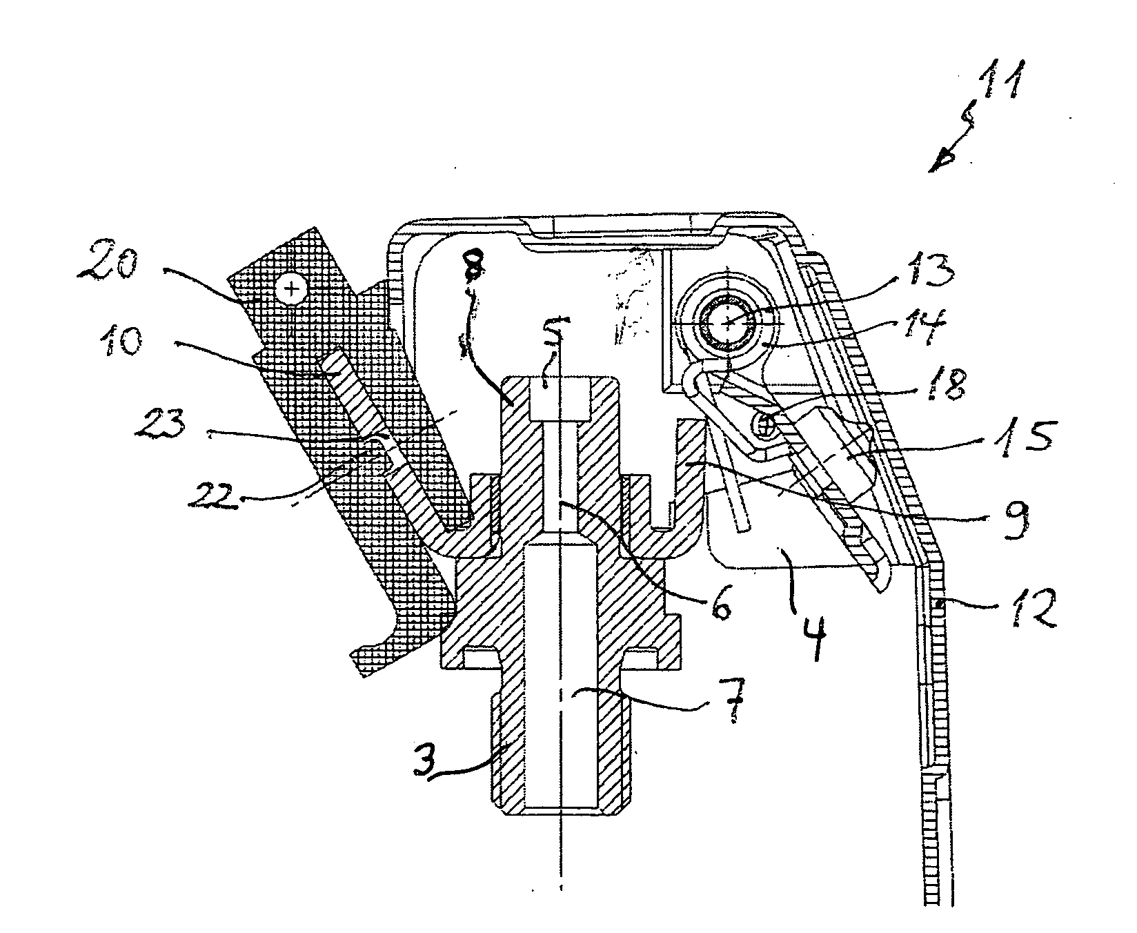
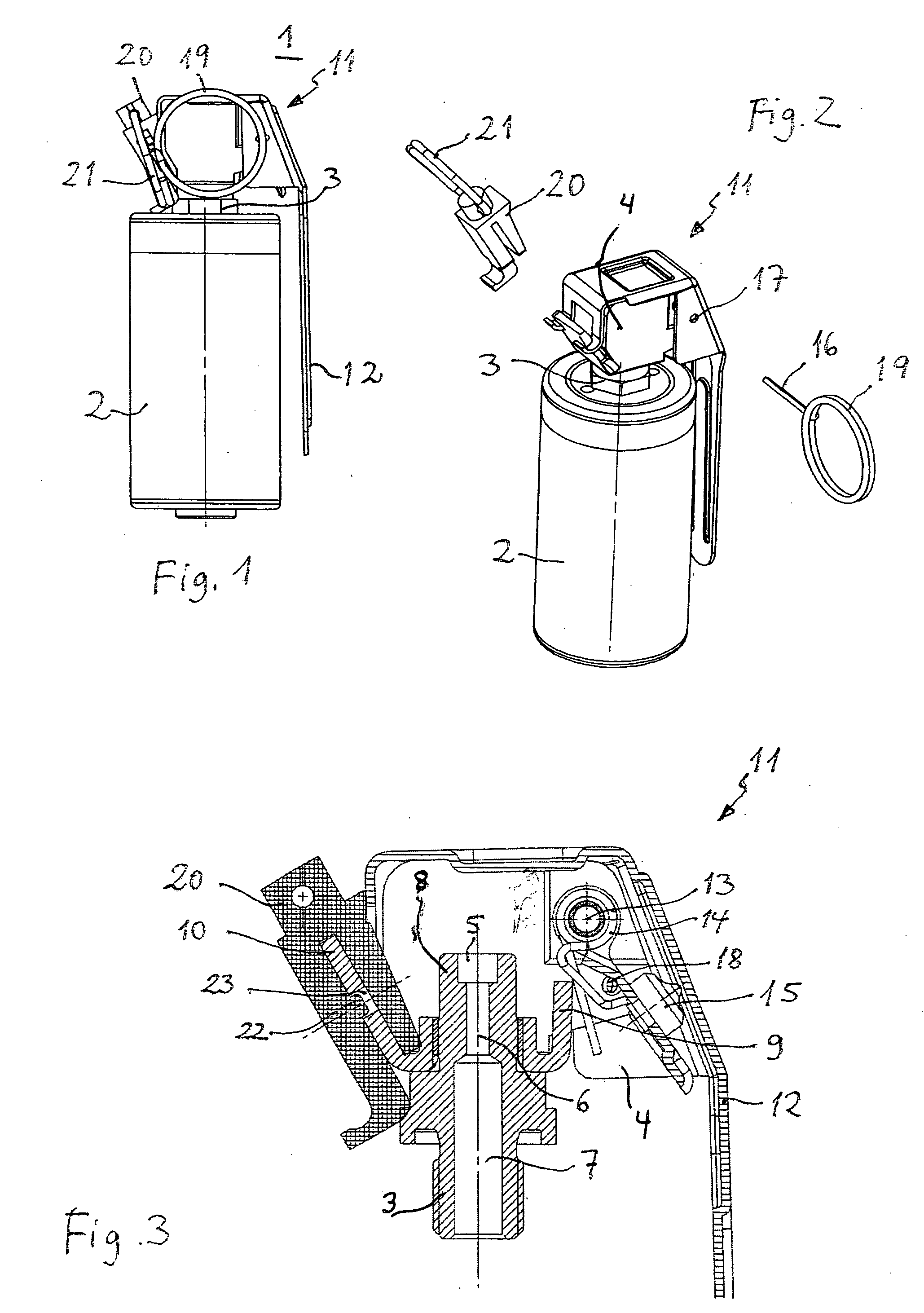
[0012] The second mechanical securing device increases safety against undesired or inadvertent triggering of the rocker-arm igniter since the user is forced to employ a controlled procedure to arm the rocker-arm igniter. If the user inadvertently removes the first securing device, or if it is otherwise removed without the irritation grenade being held securely, triggering of the rocker-arm igniter is prevented by the second securing device. The user, after noticing the removal of the first securing device, must hold the irritation grenade securely in the hand before removing the second securing device.
[0015] In an advantageous embodiment of the invention, the second mechanical securing device is positioned radially opposite the rocker arm resting against the housing so that there is good spatial separation between the two securing devices.
[0016] The two securing device elements are preferably so configured that they must be removed in different directions. This also requires more attention by the user to achieve a controlled arming of the rocker-arm igniter, and prevents inadvertent arming of the rocker-arm igniter.
[0018] One leg of the clamp is preferably provided with an engaging projection such as a small knob that engages with a corresponding engagement recess of the wing. This prevents the clamp from being removed from its rest position inadvertently when, for example, the irritation grenade is loaded. On the other side, the knob is so shaped that the fork may be extracted from the engagement recess with a strong pull.

Problems solved by technology

In unforeseen situations, it may occur that the extraction ring catches on an object, for example, and the securing pin is extracted inadvertently.
The pressure wave thus arising may lead to severe injury to the user.
There may also be situations in which the user inadvertently does not correctly hold the irritation grenade and does not hold the rocker arm securely.
If the user then extracts the securing devices, the irritation grenade loads are ignited, again leading to serious injury.

Method used


Image

  • Rocker-arm igniter
  • Rocker-arm igniter

Examples


Embodiment Construction

[0024] The preferred embodiments of the present invention will now be described with reference to FIGS. 1-3 of the drawings. Identical elements in the various figures are designated with the same reference numerals.

[0025] The irritation grenade 1 shown in FIG. 1 includes a housing 2 in which several pyrotechnic irritation charges such as report or flash charges are mounted as may be taken from the State of the Art described above. The neck 3 of a rocker-arm igniter 11 is threaded into the center of the upper side of the housing 2, whereby this neck 3 is a part of the housing 4 of the rocker-arm igniter. An ignition cap 5 is provided on the upper end of the neck facing away from the housing 2 that can ignite a delay charge 7 for the pyrotechnic loads within the housing 2 via a channel 6. The neck 3 with the igniter cap 5 forms an ignition chamber 8. Two wings 9 and 10 connected to each other are threaded onto the igniter chamber 8 that lie opposite each other and possess a straight ...


PUM


Abstract

A rocker-arm igniter for irritation grenades, hand grenades, smoke or fog grenades, or similar, includes a rocker arm that may be pivoted by a tensioned spring about a pivot axis from a initial position into a second position, and that is firmly attached to a striker that, when the rocker arm is pivoted into its second position, strikes a igniter element of the rocker-arm igniter. A first mechanical securing device with a first securing device element is provided that holds the rocker arm in its initial position. Additionally, a second mechanical securing device with a second securing device element is provided that also holds the rocker arm in its initial position. The rocker arm is released to pivot into its second position only after removal of both securing device elements.

Description

BACKGROUND OF THE INVENTION [0001] The invention relates to a rocker-arm igniter as is used for irritation grenades, hand grenades, smoke, or fog grenades. [0002] The rocker-arm igniter includes a housing in which a rocker arm may pivot about an axis with the help of a strong, pre-tensioned spring. The rocker arm is connected with a striker that strikes an ignition cap positioned in an igniter head when the spring pivots the rocker arm. [0003] The function of the rocker arm will be explained in connection with an irritation grenade. [0004] Such munitions include a housing that receives at least one, and often several, pyrotechnic loads, e.g., irritation loads that create a loud report and / or a flash of light upon ignition. A rocker-arm igniter is preferably threaded into the top part of the irritation grenade housing. For this, the rocker arm rests approximately against the housing of the irritation grenade, and is held in this initial position by a mechanical securing device, usual...

Claims


Application Information

Patent Timeline
IPC IPC(8): F42B27/00F42C14/02F42C15/20
CPCF42C14/02
Inventor LUEBBERS, THORSTENLUEBBERS, KAI
Owner NICO PYROTECHNIK HANNS JUERGEN DIEDRICHS GMBH & CO KG
Learn More