
Transaxle unit with integrated power take-off unit and torque coupling device

a technology of torque coupling device and power take-off unit, which is applied in mechanical equipment, transportation and packaging, and suv's and trucks, can solve the problems of lsd assemblies, especially those controlled by friction clutches, that are difficult to integrate into enhance performance and cost, and reduce tooling and manufacturing costs. , the effect of reducing the redesign of the fwd transaxle uni

Inactive Publication Date: 2006-12-21
DANA AUTOMOTIVE SYST GRP LLC
View PDF24 Cites 34 Cited by
  • Summary
  • Abstract
  • Description
  • Claims
  • Application Information

AI Technical Summary

Benefits of technology

[0010] Such an arrangement of the vehicular transaxle unit allows to readily modify a front-wheel-drive (FWD) powertrain architecture into an all-wheel-drive, minimizes the FWD transaxle unit redesign, tooling and manufacturing expenses, and provides active control of the differential assembly. The integrated power take-off unit and a torque-coupling device of the present invention can be integrated into the transaxle unit without any substantial modification thereof. Moreover, the torque capacity of the torque-coupling device can be actively controlled electronically to match various vehicle operating conditions.

Problems solved by technology

Such AWD vehicles are typically based on a rear wheel drive arrangement and, as such, are generally limited to SUV's and trucks.
However, the LSD assemblies, especially those controlled by a friction clutch, are difficult to integrate into the FWD transaxle unit due to the packaging constraints.
Known FWD transaxle of the all-wheel drive motor vehicles are susceptible to improvements that may enhance their performance and cost.

Method used


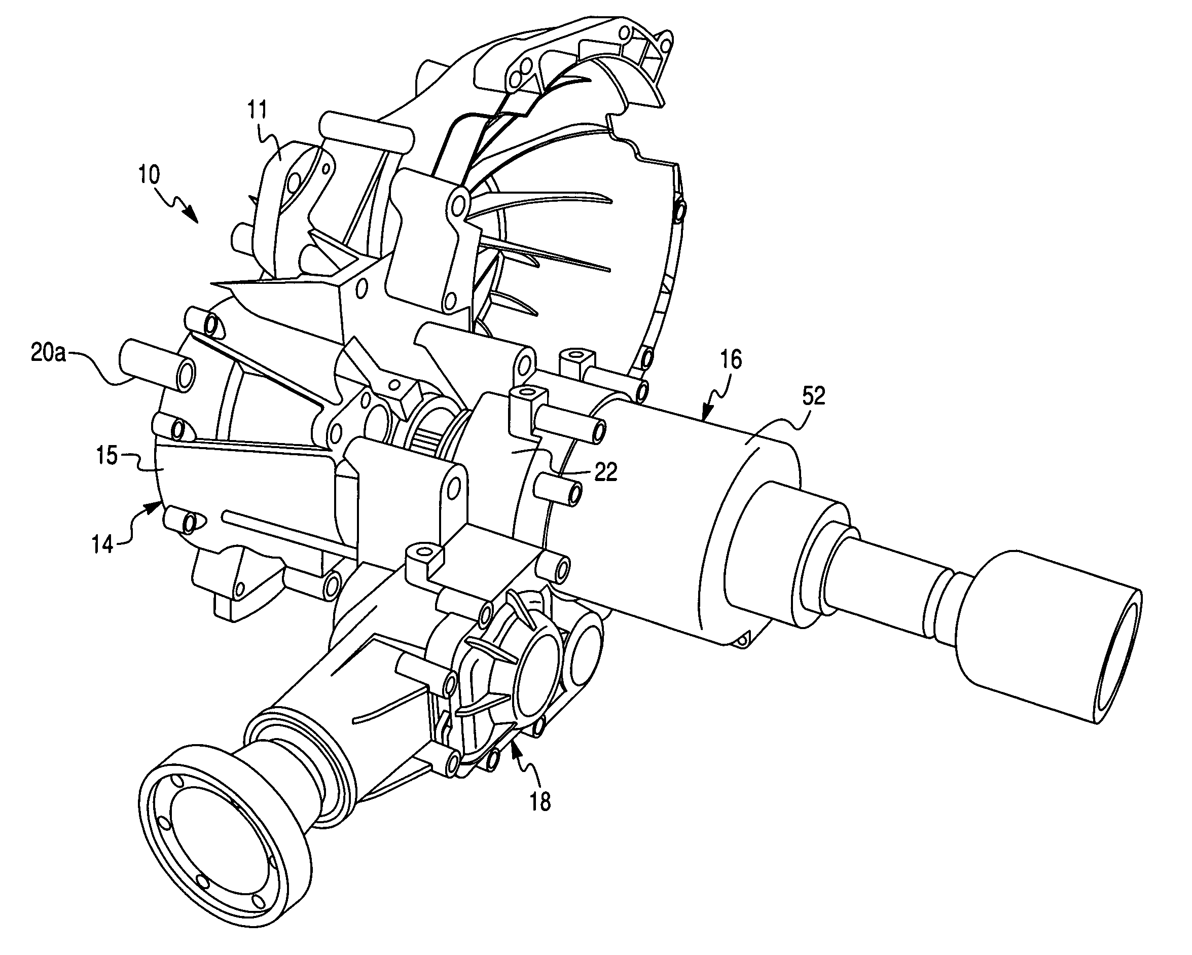
Image

  • Transaxle unit with integrated power take-off unit and torque coupling device
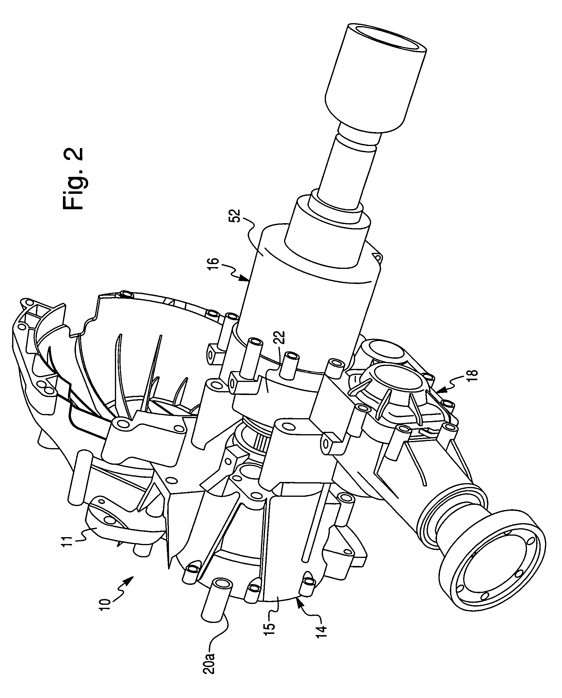
  • Transaxle unit with integrated power take-off unit and torque coupling device
  • Transaxle unit with integrated power take-off unit and torque coupling device

Examples


Embodiment Construction

[0020] The preferred embodiment of the present invention will now be described with the reference to accompanying drawings.

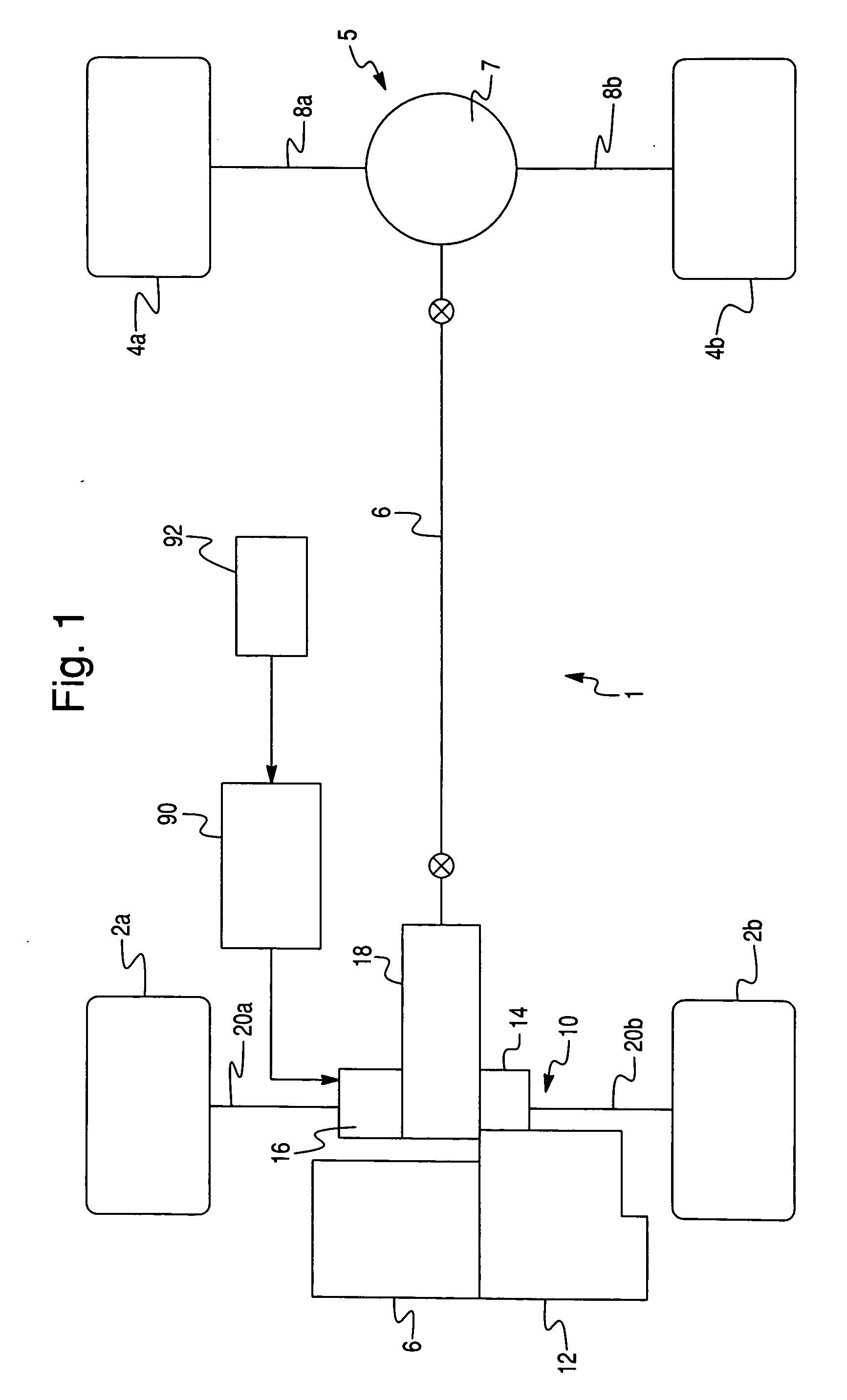
[0021] The present invention is directed to a front-wheel-drive transaxle unit with an integrated power take-off unit (PTU) and torque-coupling device for use in an all-wheel drive or four-wheel-drive motor vehicle equipped with an mounted engine and transmission and which is arranged to provide a full-time four-wheel drive mode of operation. The specific arrangement of the front-wheel-drive transaxle unit of the present invention provides a compact package which permits use of the power take-off unit in a wide variety of all-wheel drive vehicles. Although, the preferred embodiment of the present invention is described with the reference to the front-wheel-drive transaxle unit, it will be appreciated that the present invention is equally applicable to a rear-wheel-drive transaxle unit

[0022]FIG. 1 schematically depicts a drivetrain 1 of an all-wheel drive (AWD)...


PUM


Abstract

A transaxle unit comprises a differential assembly having a differential mechanism, a power take-off unit and a torque-coupling device for selectively restricting differential rotation of a differential mechanism. The torque-coupling device includes a friction clutch assembly for selectively frictionally engaging and disengaging a differential case and one of output axle shafts and a hydraulic clutch actuator. The hydraulic clutch actuator includes a hydraulic pump and a variable pressure relief valve assembly fluidly communicating with the hydraulic pump to selectively control a hydraulic pressure generated by the hydraulic pump. The variable pressure relief valve assembly comprises a valve closure member, a valve seat complementary to the valve closure member and an electro-magnetic actuator for engaging the valve closure member and generating a variable electro-magnetic force urging selectively vary a release pressure of the pressure relief valve assembly based on a magnitude of an electric current supplied to the electro-magnetic actuator.

Description

BACKGROUND OF THE INVENTION [0001] 1. Field of the Invention [0002] The present invention relates to transaxle units of motor vehicles in general, and more particularly to a transaxle unit provided with an integrated power take-off unit and torque-coupling device. [0003] 2. Description of the Prior Art [0004] Recently, there has been a significant increase in the demand for all-wheel-drive (AWD) motor vehicles equipped with a powertrain capable of providing drive torque to all four wheels. Traditional AWD vehicles are equipped with a longitudinally-extending engine and transmission that deliver power to the input of a transfer case which, in turn, distributes the power to front and rear drive axles. As is known, some transfer cases are equipped with a transfer clutch for automatically transferring power to the front drive axle during lost traction situations to establish an “on-demand” all-wheel drive mode. Other transfer cases are equipped with an interaxle differential which funct...

Claims


Application Information

Patent Timeline
Patent Type & Authority Applications(United States)
IPC IPC(8): B60K17/16
CPCB60K17/20B60K23/04B60K17/344
Inventor KRISHER, JAMES A.
Owner DANA AUTOMOTIVE SYST GRP LLC
Learn More