Balanced circuit for multi-LED driver

a multi-led driver and balanced circuit technology, applied in the direction of electric lighting sources, semiconductor devices, electric light sources, etc., can solve the problems of significant increase in current through the led string, significant shortened useful operational life of the leds in the led string, and not a cost-effective solution

Active Publication Date: 2006-12-21
AU OPTRONICS CORP
View PDF15 Cites 51 Cited by
  • Summary
  • Abstract
  • Description
  • Claims
  • Application Information

AI Technical Summary

Benefits of technology

[0008] The driving circuit of the present invention can be used in a light source of various colors by using light-emitting devices of desirable colors. For example, the light-emitting devices can have a mixture of red, green and blue light emitting devices so as to produce a white light source. The simplest white light source has a group of red light emitting devices, a group of green light emitting devices and a group of blue light emitting devices to produce red, green and blue color components. The driving circuit for this white light source has three group of current paths, each group for providing the same current to a group of color light-emitting devices. In order to achieve a desired balance among the different color components in the white light source, it is possible to adjust the number of light emitting devices of one or two colors without changing the driving circuit. Furthermore, it is possible to change the transformer coil turn ratios in an inverter driver or to use a pulse width modulator to adjust the current.

Problems solved by technology

However, because the non-linear relationship between the voltage drop and the current in an LED, one or more slightly irregular LEDs in a string may cause the current through that LED string to increase significantly.
As such, the useful operational life of the LEDs in that string may be significantly shortened.
While this type of current regulator is very effective in regulating current, it is not a cost-effective solution.
Furthermore, this type of current regulator produces a significant amount of electromagnetic radiation that could be a problematic source of electromagnetic interference (EMI).

Method used


Image

  • Balanced circuit for multi-LED driver
  • Balanced circuit for multi-LED driver
  • Balanced circuit for multi-LED driver

Examples


Embodiment Construction

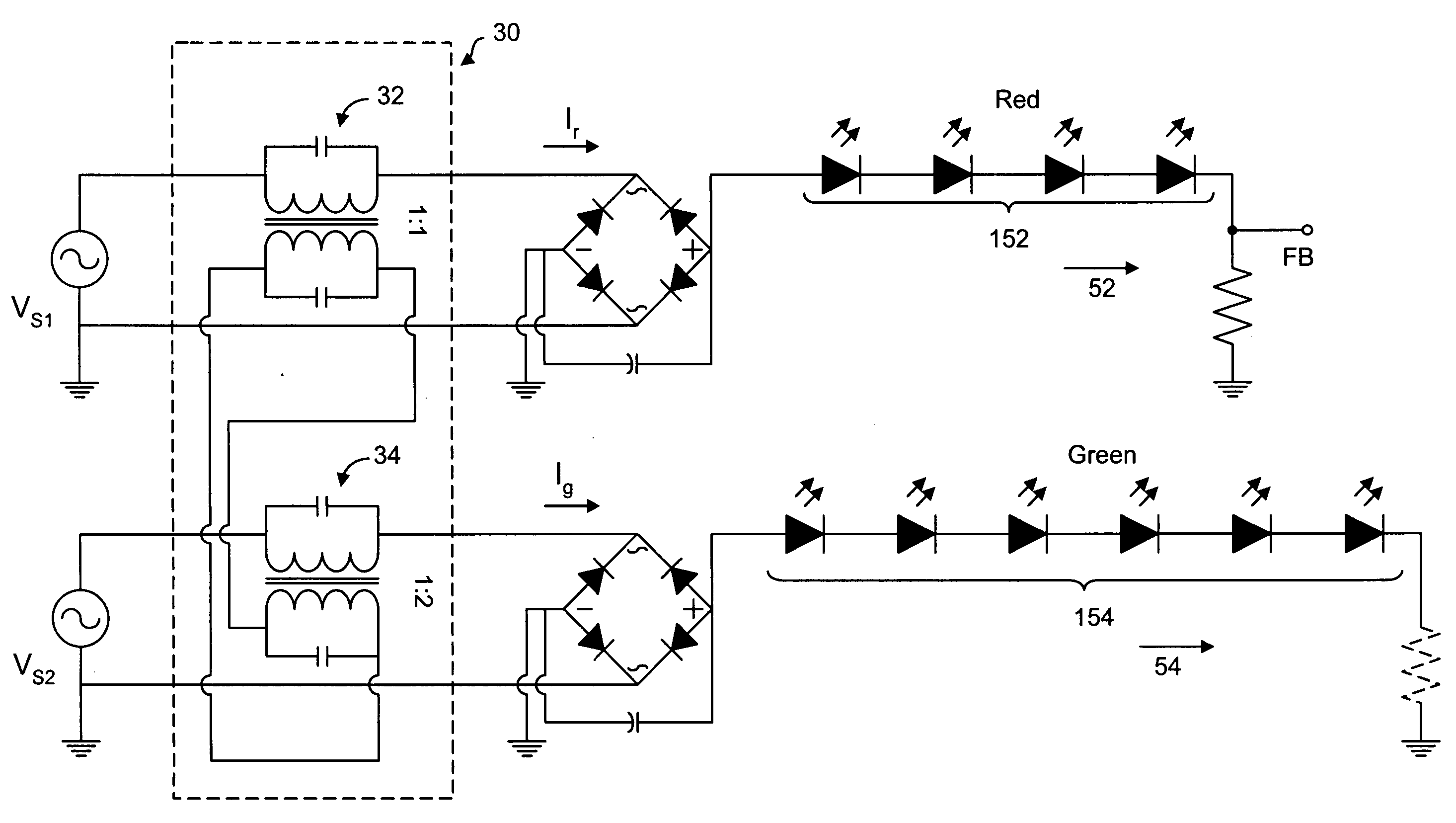
[0020] The driving circuit with a plurality of current paths for driving a plurality of light-emitting devices (LEDs), according to the present invention, is explained by way of examples as follows. FIG. 6 illustrates a lighting panel having a light source 50 and a driving circuit 10 having two current paths 52, 54 for driving two groups of LEDs 152 and 154 in the light source. The driving circuit 10 has an inverter driver block 20 operatively connected to a balanced transformer circuit 30 to provide output currents I, and 12 through a rectifier block 40. The balanced transformer circuit 30 has a first transformer 32 and a second transformer 34 coupled to each other. The rectifier 40 has a first rectifier 42 connected to the first transformer 32 and a second rectifier 44 connected to the second transformer 34. The inverter driver block 20 has a first inverter driver 22 to supply power to the first transformer 32 and a second inverter driver 24 to supply power to the second transform...


PUM


Abstract

A driving circuit uses a plurality of transformers to provide currents for driving a plurality of LEDs associated with a plurality of current paths. Each transformer has two induction coils with a coil turn ratio between to the number of turns in each induction coil. One induction coil is used to provide an output current to a different current path and the other induction coil is connected to the corresponding induction coil of other transformers for forming a current loop. The output current of each transformer has a relationship with the output current of the other transformers depending on the coil turn ratios of the connected transformers. LEDs in red, blue and green colors can be connected to different current paths so that the brightness of the LEDs in each color can be determined by the current in a current path.

Description

FIELD OF THE INVENTION [0001] The present invention relates generally to a driving circuit for driving a plurality of light-emitting devices and, more particularly, to a driving circuit having a plurality of current paths each of which is connected to one or more light-emitting devices. BACKGROUND OF THE INVENTION [0002] Light-emitting devices (LEDs) are commonly used in a back-lighting source for a liquid crystal display (LCD) panel. In particular, LEDs in red, green and blue colors are used to provide a back-lighting source in “white” color. In prior art, when a driving circuit is used to drive a display having one or more strings of light-emitting devices (LEDs), these strings are connected in parallel to form a single current supply path. As shown in FIG. 1, a current limiting device and a current limiting resistor Rcl are used to regulate the total current in the current supply path. In such a driving circuit, a voltage boosting device is used as a power supply to supply the cu...

Claims


Application Information

Patent Timeline
Patent Type & Authority Applications(United States)
IPC IPC(8): H05B41/24H01L33/00
CPCH05B33/0809H05B45/35
Inventor WEY, CHIN-DERYU, YA-YUNLI, HSIEN-JENLEE, YUEH-PAO
Owner AU OPTRONICS CORP
Why Eureka
Try Eureka