Composite surveillance camera system

a camera system and surveillance technology, applied in the field of surveillance systems, can solve the problems of significant events going undetected, the remaining portion of the scene cannot be viewed, and it is difficult to direct the pzt camera at events in a timely manner

Inactive Publication Date: 2006-12-21
MITSUBISHI ELECTRIC RES LAB INC
View PDF1 Cites 24 Cited by
  • Summary
  • Abstract
  • Description
  • Claims
  • Application Information

AI Technical Summary

Problems solved by technology

However, while the camera is directed on the small portion of the scene, the remaining portion of the scene cannot be viewed.
However, as a disadvantage, the wide angle and detailed images cannot be acquired at the same time, which may cause some significant events to go undetected.
This problem is repeated every time the configuration of the environment changes.
If the system is operated manually, it may be difficult to direct the PZT camera at events in a timely manner, due to the perceptual gap between the sensor network observations, and the PTZ control space.
As a disadvantage, extremely wide-angle refractive lenses a

Method used


Image

  • Composite surveillance camera system
  • Composite surveillance camera system
  • Composite surveillance camera system

Examples


Embodiment Construction

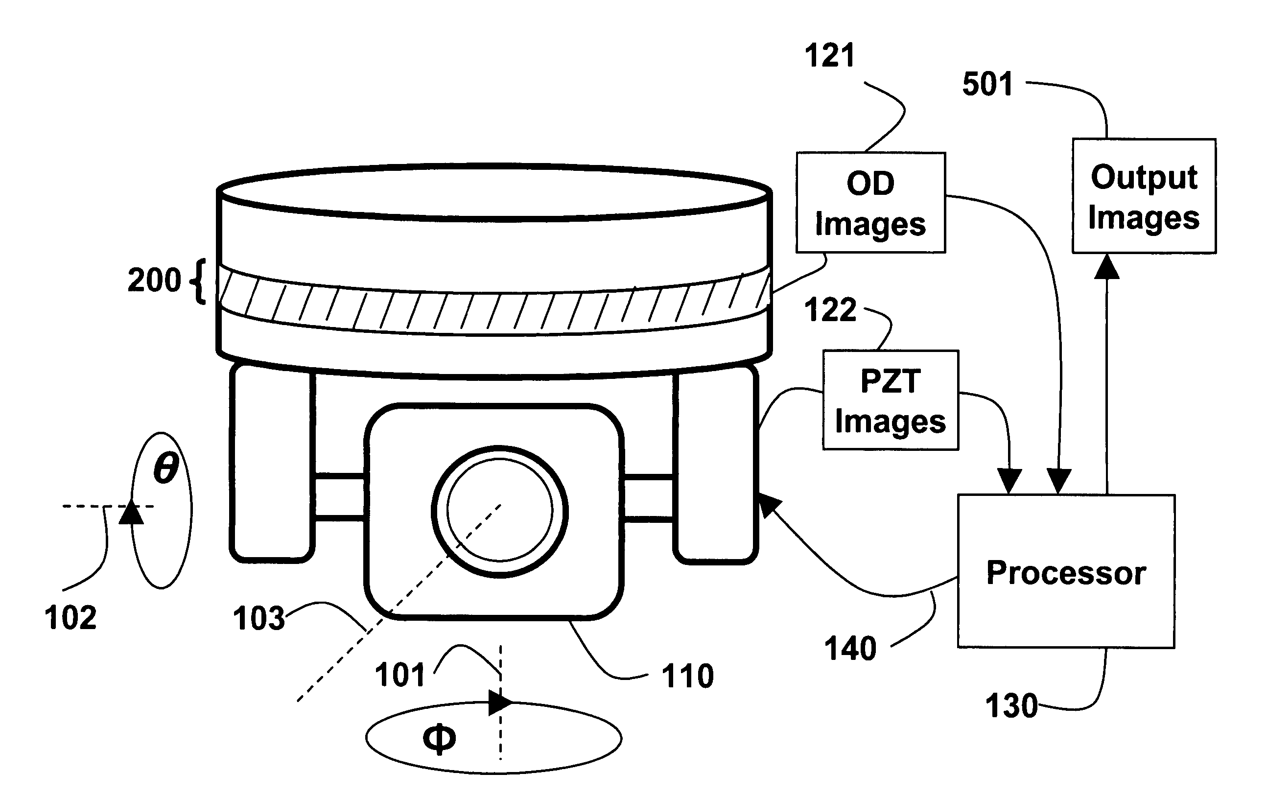
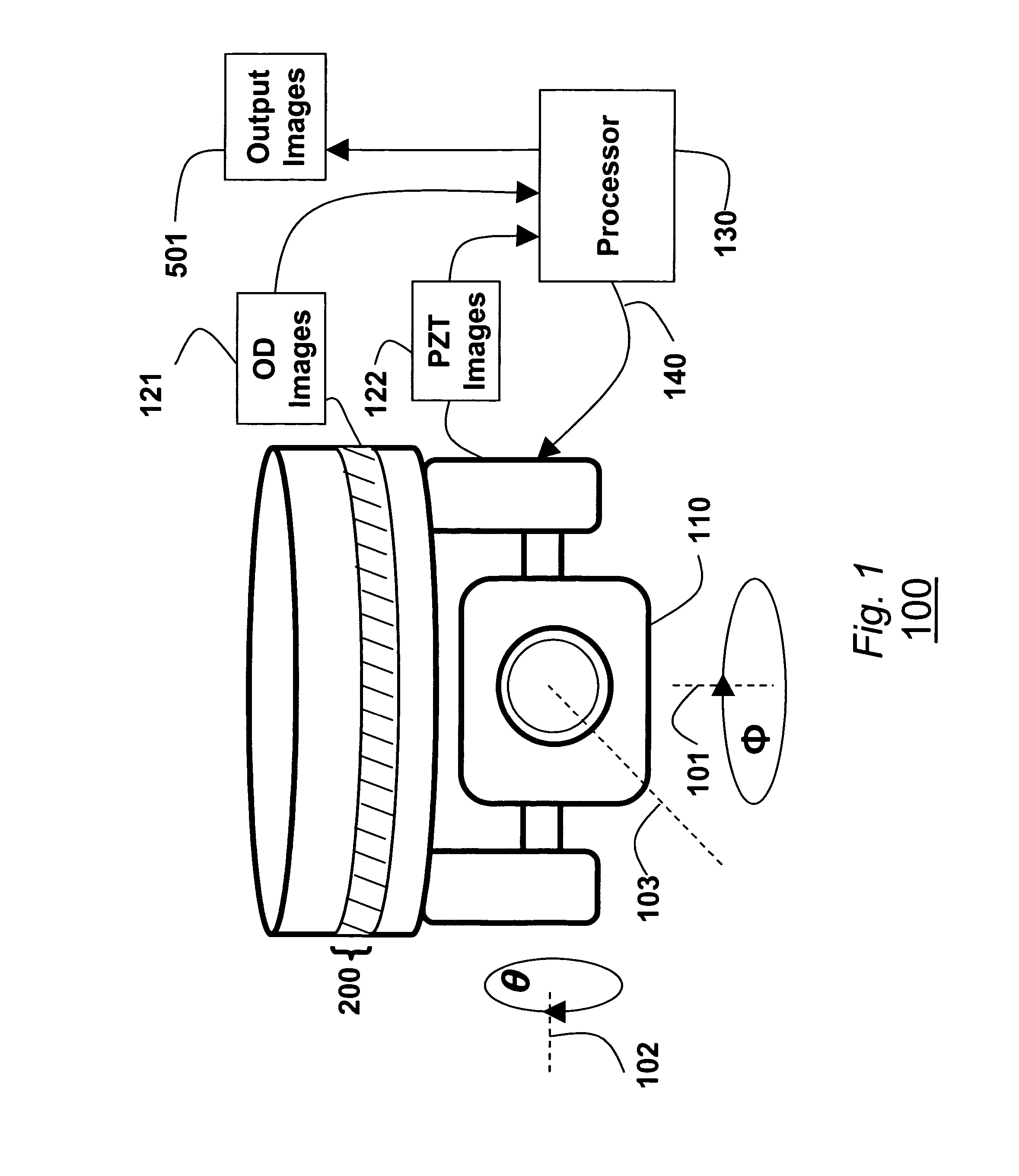
[0018]FIG. 1 shows a composite camera 100 according to one embodiment of the invention. The composite camera 100 includes an omni-directional (OD) imager 200, and a pan-tilt-zoom (PZT) imager 110. The optical centers of the OD and PZT imagers are substantially colocated. That is, any difference in their locations can be ignored for practical applications, as described below.

[0019] The OD imager 200 acquires OD images 121 of a scene. The PTZ imager 110 is mounted to rotate about a vertical axis 101 and a horizontal axis 102. The PZT imager can also zoom along an optical axis 103 of the imager. The PZT imager acquires PZT images 122 of the scene. The OD images 121 are processed by processor 130 as described below. The result of the processing can then be used to direct 140 the PTZ imager 110 at events in the scene. Events can be moving objects, e.g., people, cars, and / or doors; or changes in the environment, e.g., water, smoke, and / or fire. The processor can also generate output imag...


PUM


Abstract

A method and apparatus acquires images of a scene with an omni-directional imager and a pan-tilt-zoom imager. A relationship between pixels in the input image and locations in the scene is expressed in terms of polar coordinates. An event is detected in the input images and the omni-directional pan-tilt-zoom camera is directed at the event in the scene using the relationship expressed in the polar coordinates.

Description

FIELD OF THE INVENTION [0001] This invention relates generally to surveillance systems, and more particularly to surveillance systems that use pan-tilt-zoom cameras. BACKGROUND OF THE INVENTION [0002] A pan-tilt-zoom (PTZ) camera can acquire a high angular resolution image or video of a small portion of a hemispherical scene by setting the field of view to a narrow angle. However, while the camera is directed on the small portion of the scene, the remaining portion of the scene cannot be viewed. Several solutions to this problem are known. [0003] Temporal Multiplexing [0004] In temporal multiplexing, the field of view of the PZT camera is normally set to a very wide angle and short focal length to acquire low detail, wide field of view images. When more detail is required, the PZT camera is directed at a particular portion of the scene to acquire narrow field of view images. Typically, this is done manually. For example, a user locates a significant surveillance event in the scene f...

Claims


Application Information

Patent Timeline
IPC IPC(8): H04N7/00H04N5/225H04N7/18
CPCH04N5/232H04N5/2258H04N23/45H04N23/695
Inventor WREN, CHRISTOPHER R.AZARBAYEJANI, ALI J.DIETZ, PAUL H.
Owner MITSUBISHI ELECTRIC RES LAB INC
Why Eureka
Try Eureka