Detachable rolling-element retainer

Active Publication Date: 2006-12-21
HIWIN TECH
View PDF8 Cites 7 Cited by
  • Summary
  • Abstract
  • Description
  • Claims
  • Application Information

AI Technical Summary

Benefits of technology

[0009] The primary objective of the present invention is to provide a low cost rolling element retainer, besides being capable of preventing disengagement of the rolling element, the retainer is also de

Problems solved by technology

However, this type slide block still has some disadvantages that need to be improved:
First, disposing the five parts of the retainer precisely in the rolling groove 12 of the slide block 11 is ti

Method used


Image

  • Detachable rolling-element retainer
  • Detachable rolling-element retainer
  • Detachable rolling-element retainer

Examples


Embodiment Construction

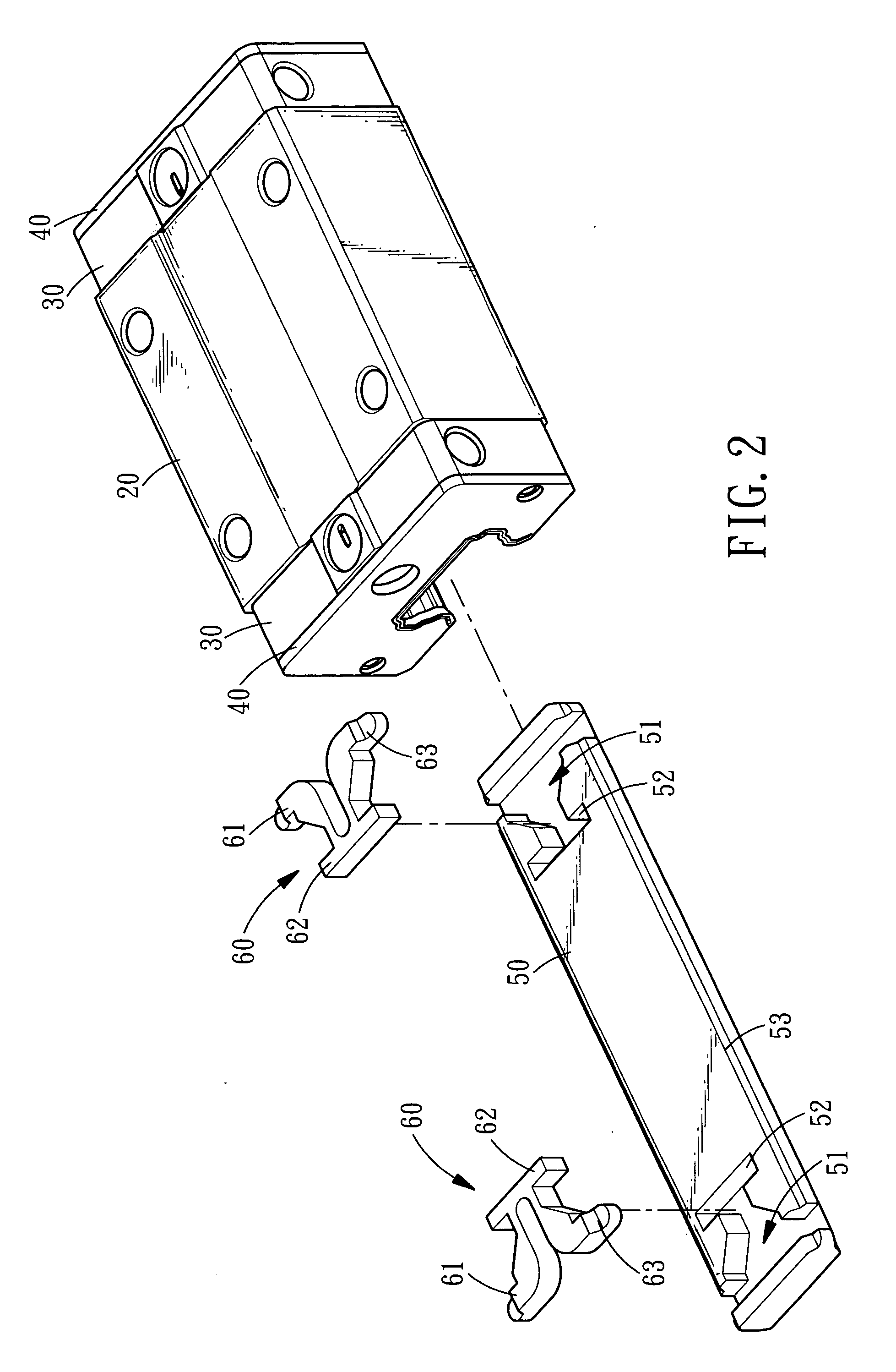
[0022] Referring to FIGS. 2 and 3, a detachable rolling-element retainer in accordance with a first preferred embodiment of the present invention is shown and comprises: a slide block 20, a pair of end caps 30, a pair of scrapers 40, a base 50 and a pair of stoppers 60.

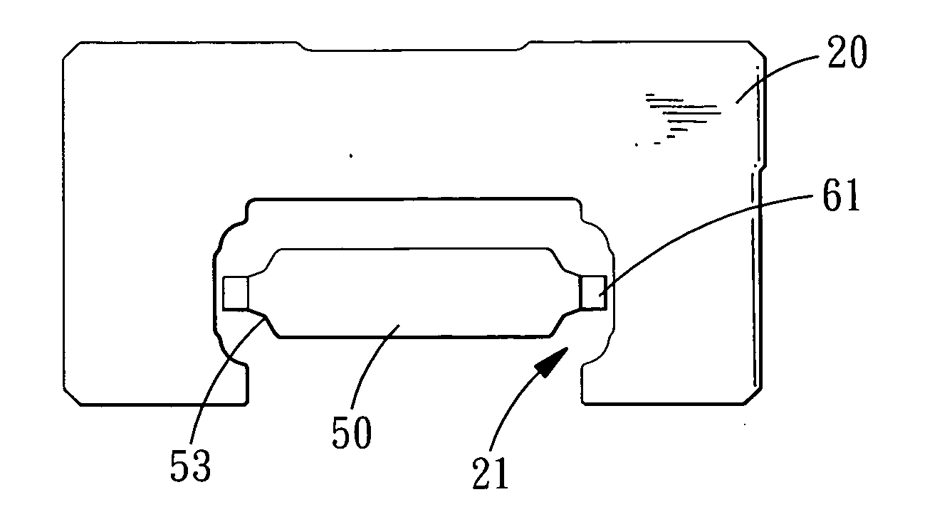
[0023] The slide block 20 is provided at its bottom with a slide groove 21 (with reference to FIG. 4), and to either end of the slide block 20 are attached the end cap 30 and the scraper 40.

[0024] The base 50 provided at either end thereof with a cavity 51 in which defined a positioning slot 52. The base 50 is moveably received in the slide groove 21 and provided with concave retaining portions 53 for mating with the sliding elements inside the slide groove 21 of the base 50.

[0025] The stoppers 60 each include a pair of flexible stopping portions 61 and a protrusive positioning portion 62 that are to be engaged in the positioning slots 52 of the cavities 51 of the base 50 (as shown in FIG. 7) in such manner that th...


PUM


Abstract

A detachable rolling-element retainer comprises: a slide block defined with a slide groove in which disposed a plurality of rolling elements and a base inserted in the slide groove of the slide block. The base is provided at either end thereof with elastic deformable stopping portions. One of the stopping portions is positioned at an end of the slide block after being compressed in to and passing through the slide groove, while another one of the stopping portions is positioned at another end of the slide block, thus enabling the base of the rolling-element retainer to be inserted into or disengaged from the slide groove of the slide block easily while preventing disengagement of the rolling elements from the slide block.

Description

BACKGROUND OF THE INVENTION [0001] 1. Field of the Invention [0002] The present invention relates to a detachable rolling-element retainer, with which, disengagement of rolling elements from the slide block can be prevented during assembly of the slid block. [0003] 2. Description of the Prior Arts [0004] A conventional rolling element retainer used on a slide block as shown in FIG. 1 generally comprises an upper part 13, a pair of mid parts 14 and a pair of lower parts 15 that are disposed in a slide groove 12 of a slide block 11 and cooperate to prevent disengagement of the rolling elements from the slide block 11. However, this type slide block still has some disadvantages that need to be improved: [0005] First, disposing the five parts of the retainer precisely in the rolling groove 12 of the slide block 11 is time consuming and requires high level of skill. [0006] Second, the respective parts 13, 14 and 15 of the retainer have different shapes and only can be made by different m...

Claims


Application Information

Patent Timeline
IPC IPC(8): F16C29/06
CPCF16C41/045F16C29/0647
Inventor LIN, YUN-YINCHEN, JIN-SHENG
Owner HIWIN TECH
Why Eureka
Try Eureka