Eureka AIR delivers breakthrough ideas for toughest innovation challenges, trusted by R&D personnel around the world.

Battery pack having elastic body inserted between members for holding cell modules and frame of battery pack

Inactive Publication Date: 2006-12-21
HONDA MOTOR CO LTD
View PDF1 Cites 45 Cited by
  • Summary
  • Abstract
  • Description
  • Claims
  • Application Information

AI Technical Summary

Benefits of technology

[0008] In light of the above circumstances, an object of the present invention is to provide a battery pack for avoiding an unstable state of the cell modules in a cell box.
[0014] In accordance with the above structure, a dimensional error due to stacking the cell modules can be canceled by compression of the elastic body, thereby pushing and holding the cell modules in the cell box by the elastic body. As a result, it is possible to avoid an unstable state of the cell modules in the cell box, and unnecessary noise due to the unstable state.
[0019] In accordance with the above structure, it is possible to substantially uniformly apply force via the pushing member to the cell modules.
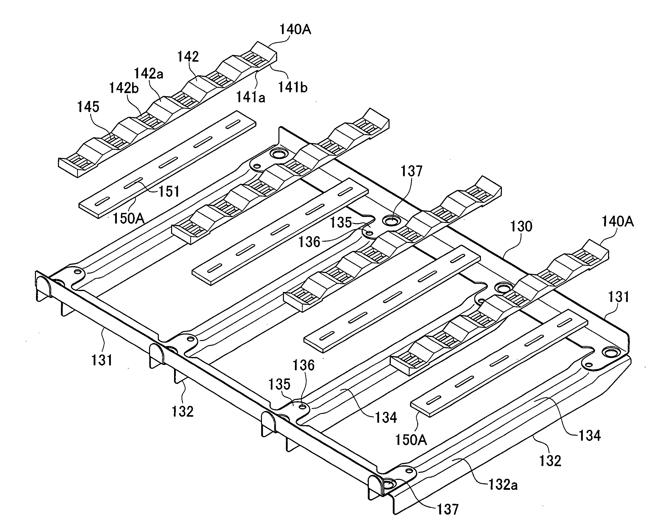
[0020] The elastic body (e.g., an elastic body 150B in an embodiment explained later) may be made using a metal plate spring, and have hooks (e.g., hooks 156 in the embodiment) hooks between which a part of the frame is positioned, which push the part of the frame. In accordance with the above structure, it is possible to easily fasten the elastic body to the frame by pushing the frame using the hooks between which a part of the frame is positioned.

Problems solved by technology

When the cell modules are stacked in a manner such that corresponding outer faces of the holding members of adjacent cell modules contact each other, heights of upper ends of the cell modules in the top row may not be uniform due to an error in dimension between the holding members, or the like.
If the cell modules, arranged in a zigzag while having such an error, are contained in a cell box, the cell modules are unstable in the cell box.
In particular, when such a cell box is installed in a vehicle, the cell modules may be shaken due to the movement of the vehicle, which may cause unnecessary noise.

Method used


Image

  • Battery pack having elastic body inserted between members for holding cell modules and frame of battery pack
  • Battery pack having elastic body inserted between members for holding cell modules and frame of battery pack
  • Battery pack having elastic body inserted between members for holding cell modules and frame of battery pack

Examples


first embodiment

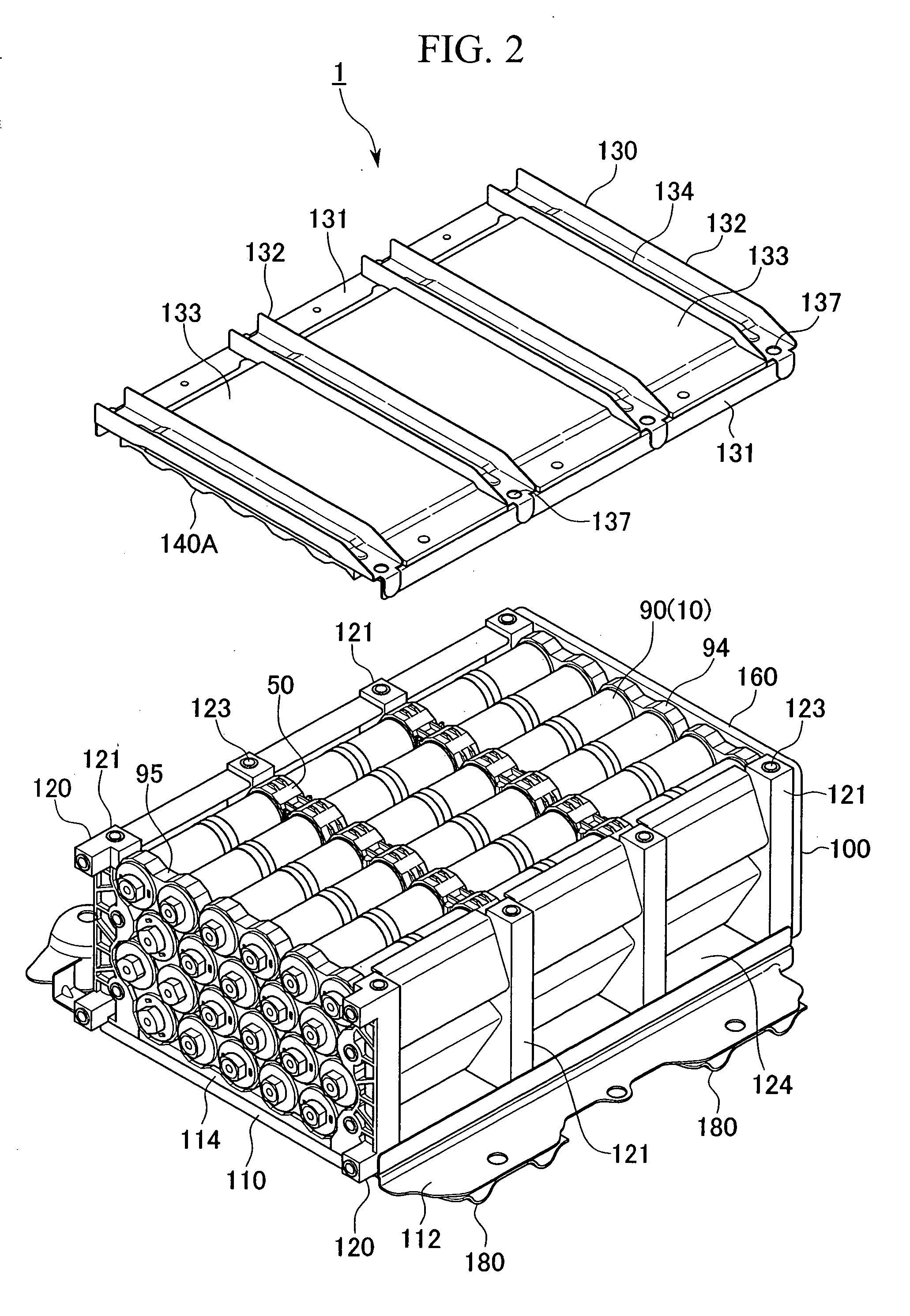
[0034] A first embodiment of the battery pack of the present invention will be explained with reference to FIGS. 1 to 7. A battery pack 1 of the present embodiment is attached to a back face of a seat in an electric vehicle.

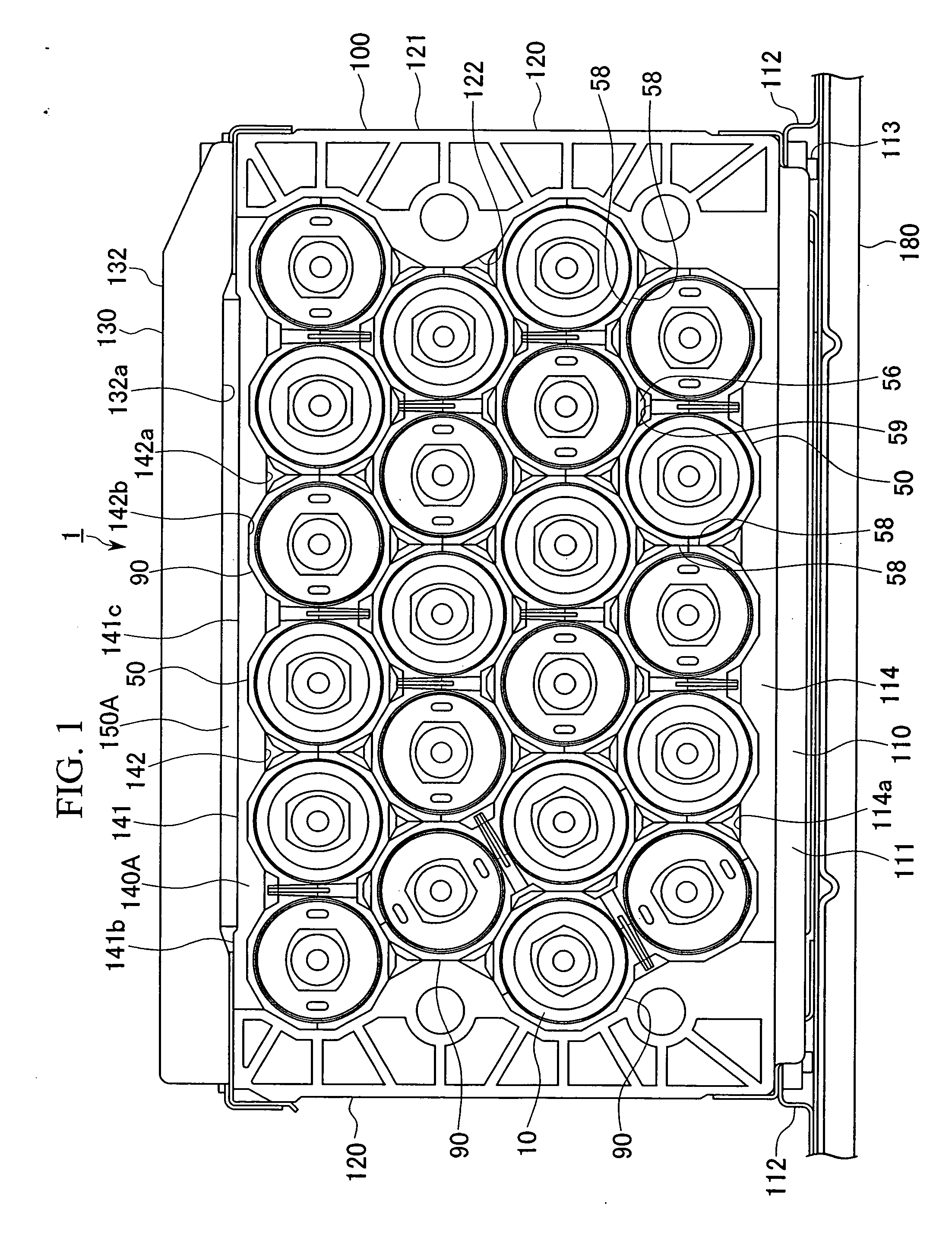
[0035]FIG. 1 is a general front view of the battery pack 1 having a cell box 100 in which a plurality of cell modules 10 (22 modules in the present embodiment) are contained in a manner such that the axes of the cell modules 10 are parallel to each other. As shown in FIG. 5, in this battery pack 1, pairs of cell modules 10 are respectively bound together in advance by using grommets 50 (i.e., holding members), so as to form cell module units 90. A plurality of the cell module units 90 are stacked in a manner such that outer faces of the grommets 50 of adjacent cell module units 90 contact each other, and thereby the cell modules 10 are arranged in a manner such that the axes of the cell modules 10 are parallel to each other. Accordingly, a specific gap is produc...

second embodiment

[0065] A second embodiment of the present invention will be explained with reference to FIGS. 8 and 9. In comparison with the battery pack 1 of the first embodiment, a battery pack 1000 of the second embodiment has distinctive features in the upper frame 130, pushing members 140B, and elastic bodies 150B. Other structural elements are identical to those of the first embodiment, and thus are given identical reference numerals or symbols, and explanations thereof are omitted.

[0066] In the battery pack 1 of the above-described first embodiment, the pushing members 140A and the elastic bodies 150A are attached to the upper frame 130 in advance. However, in the battery pack 1000 of the second embodiment, the elastic bodies 150B are attached to the upper frame 130 in advance, but the pushing members 140B are not attached to the upper frame 130 and are just disposed on the grommets 50, the bus-bar covers 94, and the caps 95 of the cell module units 90.

[0067] Due to the difference between...


PUM


Abstract

A battery pack includes a plurality of cylindrical cell modules, each formed by serially connecting a plurality of unit cells; a cell box in which the cell modules are contained in a manner such that the cell modules are arranged parallel to each other; a plurality of holding members fit to outer peripheries of the cell modules so as to arrange the cell modules in a zigzag manner along axes of the cell modules, in a manner such that the holding members make contact with each other and a gap is secured between every adjacent cell module; and an elastic body inserted between the holding members and a frame of the cell box. Preferably, a pushing member provided between the elastic body and the holding members is provided.

Description

BACKGROUND OF THE INVENTION [0001] 1. Field of the Invention [0002] The present invention relates to a battery pack formed by arranging and containing a plurality of cell modules in parallel to each other in a cell box. [0003] Priority is claimed on Japanese Patent Application No. 2005-176227, filed Jun. 16, 2005, the content of which is incorporated herein by reference. [0004] 2. Description of the Related Art [0005] A battery pack may be formed by stacking cylindrical cell modules in a cell box in a zigzag form, where each cell module is formed by serially connecting a plurality of unit cells (see Reference Document 1: Japanese Unexamined Patent Application, First Publication No. 2003-308816). In the battery pack disclosed in Reference Document 1, holding members, each having a polygonal section, are attached to the outer periphery of each cell module at specific intervals along the axis of the cell module, and a plurality of the cell modules are stacked in a zigzag in a manner su...

Claims


Application Information

Patent Timeline
IPC IPC(8): H01M2/10
CPCH01M6/42H01M2/105H01M50/213
Inventor MATSUOKA, TOSHIYUKIMIZUTANI, ATSUSHI
Owner HONDA MOTOR CO LTD
Why Eureka
Eureka Blog
Learn More