In-vivo collection device for blood liquid biopsy

A liquid biopsy and collection device technology, applied in the field of blood processing, can solve problems such as the insufficiency and stability of the suction process, and achieve the effects of avoiding state instability, increasing efficiency, and enriching functions

Pending Publication Date: 2022-03-04
QINGDAO BLOOD CENT
View PDF0 Cites 0 Cited by
  • Summary
  • Abstract
  • Description
  • Claims
  • Application Information

AI Technical Summary

Problems solved by technology

[0003] In the prior art, the cell collection device can be pulled into the catheter body by pulling the inflation hose. When the cell collection device needs to be pushed out of the catheter body, inflate the inflation hose to expand the inflation hose, and then push the inflated The inflatable hose pushes out the cell collection device to avoid directly inflating the cell collection device. However, the existing technology uses the inflatable hose as power for suction, and the suction process is not uniform and stable. Fixed-point or omni-directional suction, so the existing technology has a lot of room for improvement

Method used


Image

  • In-vivo collection device for blood liquid biopsy
  • In-vivo collection device for blood liquid biopsy
  • In-vivo collection device for blood liquid biopsy

Examples


Embodiment 1

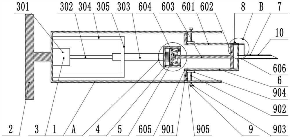
[0029] see Figure 1-4 , an in vivo collection device for blood liquid biopsy, comprising an installation cylinder 1 and a holding handle 2 fixed on the installation cylinder 1;

[0030] The telescoping mechanism 3 is fixedly connected in the installation cylinder 1;

[0031] The telescoping mechanism 3 is fixedly connected to the cartridge mechanism 4;

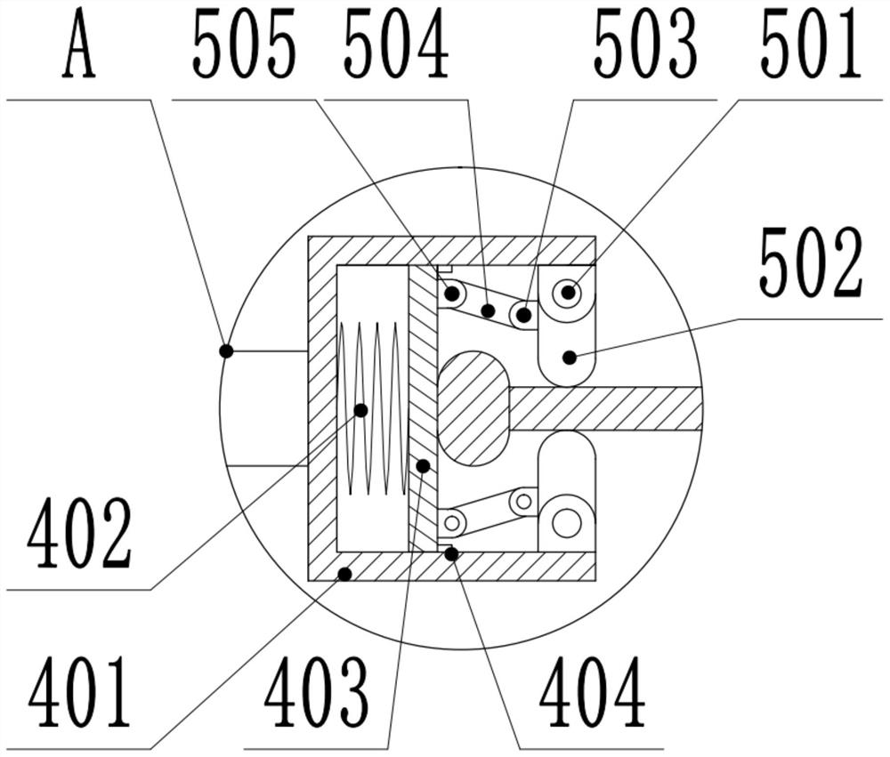
[0032] The cartridge mechanism 4 is fixedly connected to the clamp mechanism 5;

[0033] The clamping mechanism 5 is provided with a collecting cylinder mechanism 6;

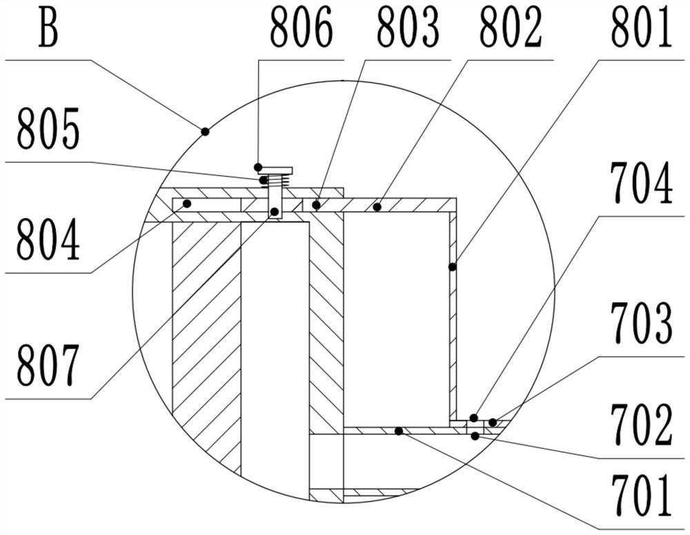
[0034] The collection cylinder mechanism 6 is fixedly connected to the needle assembly 10, and the needle assembly 10 includes a needle mechanism 7 and a positioning mechanism 8, and the positioning mechanism 8 is used for positioning and adjusting the state of the needle mechanism 7;

[0035] The mounting cylinder 1 is provided with a clamping plate mechanism 9 .

[0036] The telescopic mechanism 3 includes a motor 301 fixed in the installation cylinder 1,...

Embodiment 2

[0043] see Figure 1-4 , the other content of this embodiment is the same as that of Embodiment 1, the difference is that: the clamping plate mechanism 9 includes a limit plate 901 fixed in the installation cylinder 1, the installation cylinder 1 is threaded to the second threaded rod 902, and the second threaded rod 902 is threaded. One end of the second threaded rod 902 located on the outside of the installation cylinder 1 is fixedly connected to the clamping handle 903, and the end of the second threaded rod 902 away from the clamping handle 903 is rotatably connected to the clamping plate 904, and the side of the limiting plate 901 close to the clamping plate 904 is opened There is a clamping movement groove 905, and the side of the clamping plate 904 close to the limiting plate 901 is located in the clamping moving groove 905, and the clamping plate 904 and the limiting plate 901 are slidably connected. Specifically, the clamping handle 903 is rotated to clamp The rotatio...


PUM


Abstract

The invention discloses an in-vivo collection device for blood liquid biopsy, and relates to the technical field of blood treatment, the in-vivo collection device comprises a mounting cylinder and a holding handle fixed on the mounting cylinder; a telescopic mechanism is fixedly connected in the mounting cylinder; the telescopic mechanism is fixedly connected with the clamping cylinder mechanism; a clamping plate mechanism is fixedly connected in the clamping cylinder mechanism; a collecting barrel mechanism is arranged in the clamping plate mechanism; the collecting cylinder mechanism is fixedly connected with a needle head assembly; the needle head assembly comprises a needle head mechanism and a positioning mechanism; according to the blood suction device, the collection barrel mechanism can be driven to work by arranging the telescopic mechanism, blood suction is achieved, the clamping plate mechanism can be controlled by arranging the clamping barrel mechanism, and therefore connection with the collection barrel mechanism is achieved, and suction is completed; by arranging the positioning mechanism, the state of the needle head mechanism can be adjusted, the blood suction position is selected, the blood liquid biopsy collection efficiency is improved, and meanwhile the functions of the whole device are enriched.

Description

technical field [0001] The invention relates to the technical field of blood processing, in particular to an in vivo collection device for blood liquid biopsy. Background technique [0002] Blood is a red, opaque, viscous liquid that flows through the blood vessels and heart of a person. Blood is composed of plasma and blood cells. One liter of plasma contains 900-910 grams of water, 65-85 grams of protein and 20 grams of low-molecular substances. There are various electrolytes and organic compounds in low-molecular substances. Blood cells include red blood cells and white blood cells. and platelets three types of cells. [0003] In the prior art, the cell collection device can be pulled into the catheter body by pulling the inflation hose. When the cell collection device needs to be pushed out of the catheter body, inflate the inflation hose to expand the inflation hose, and then push the inflated The inflatable hose pushes out the cell collection device to avoid directly...

Claims


Application Information

Patent Timeline
Patent Type & Authority Applications(China)
IPC IPC(8): A61B5/15
CPCA61B5/15A61B5/150206A61B5/150381A61B5/150236A61B5/150099A61B5/150343
Inventor 孙美贞张丽成枫
Owner QINGDAO BLOOD CENT
Why Eureka
Try Eureka