Semiconductor device and information processing system including the same

Active Publication Date: 2011-04-21
LONGITUDE LICENSING LTD
View PDF7 Cites 18 Cited by
  • Summary
  • Abstract
  • Description
  • Claims
  • Application Information

AI Technical Summary

Benefits of technology

[0013]According to the present invention, output buffers of all bidirectional buffer circuits connected to the through silicon via operate as termination resistors, and thus even when the output buffers are in high impedance, the logic level of the through silicon via can be maintained. Consequently, it is possible to prevent a logic unstable state of the through silicon via and to prevent an occurrence of a through current. Further, an operation test of an interface chip alone can be performed by using a logic-level holding circuit provided in the interface chip as a pseudo memory, and thus the manufacture yield semiconductor devices can be greatly improved.

Problems solved by technology

For this reason, an area for a memory core in each memory chip is restricted to an area obtained by subtracting the area for the front end unit from a total chip area, and it is difficult to greatly increase a memory capacity for each chip (for each memory chip).
Therefore there have been a further problem that it is difficult to speed up the front end unit.
However, in a conventional chip-stacked semiconductor device having a bidirectional buffer connected to all TSVs of an interface chip and core chips, the logic level of the TSVs becomes unstable when output buffers in bidirectional buffers of all chips connected to one TSV are set at high impedance.
As a result, a through current flows to an input buffer in the bidirectional buffers and the current consumption of the semiconductor device greatly increases.
Further, because any memory element is not mounted on the interface chip, the interface chip alone cannot test a read / write operation.
Therefore, a defect of the interface chip is recognized after combining the interface chip with core chips.

Method used


Image

  • Semiconductor device and information processing system including the same
  • Semiconductor device and information processing system including the same
  • Semiconductor device and information processing system including the same

Examples


Embodiment Construction

[0026]Preferred embodiments of the present invention will be explained below in detail with reference to the accompanying drawings.

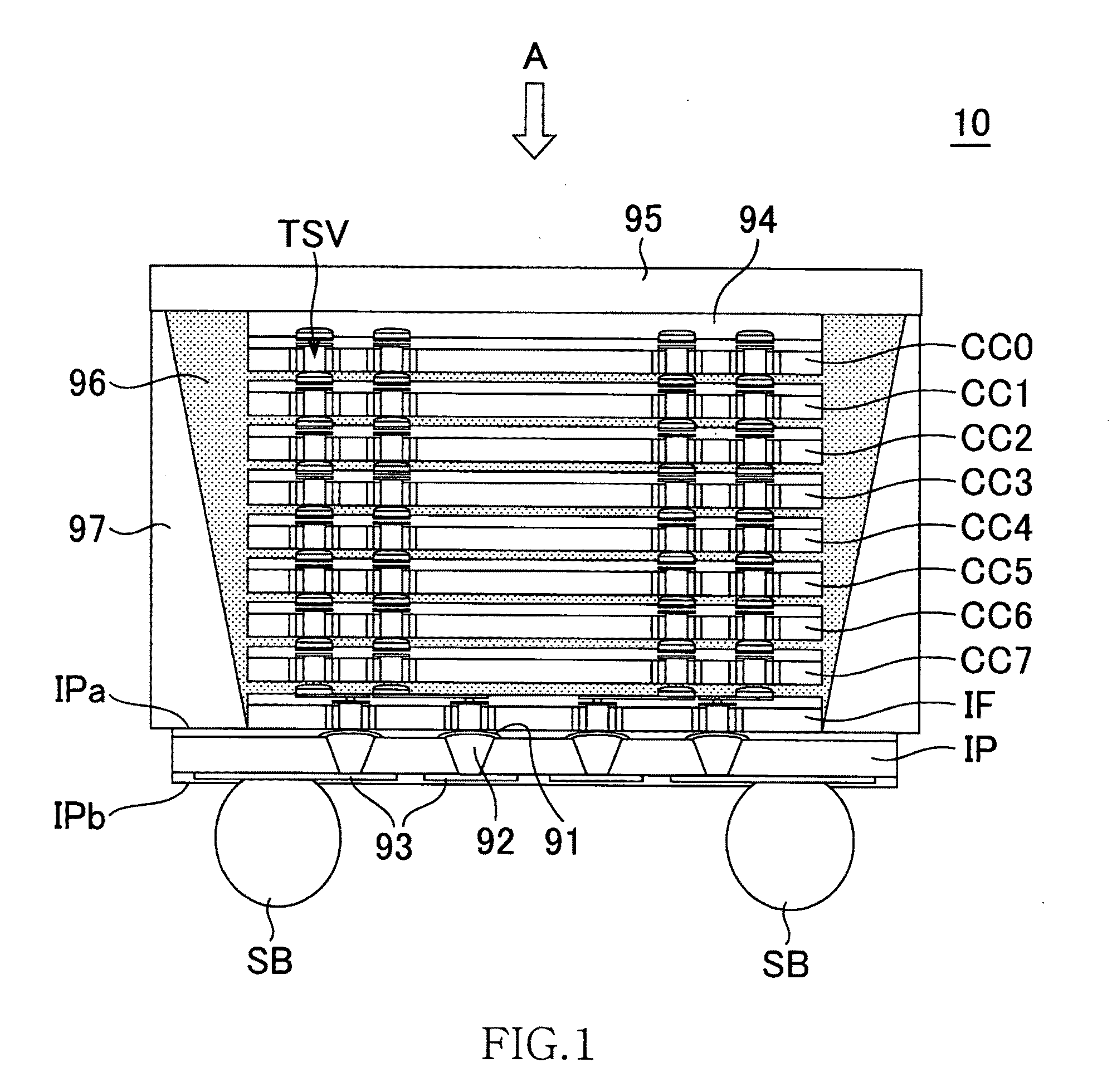
[0027]FIG. 1 is a schematic cross-sectional view illustrating the structure of a semiconductor device according to the preferred embodiment of the present invention.

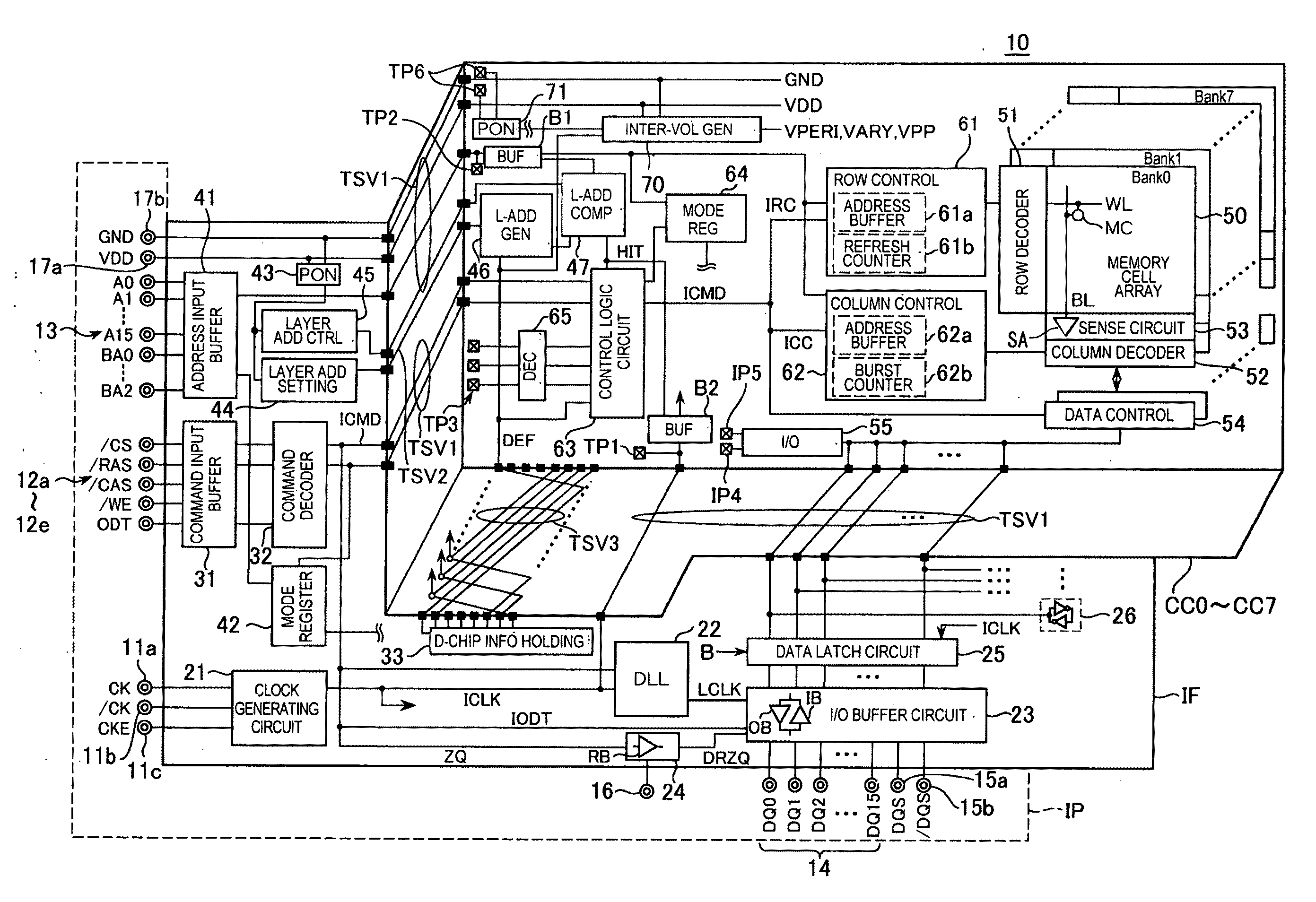
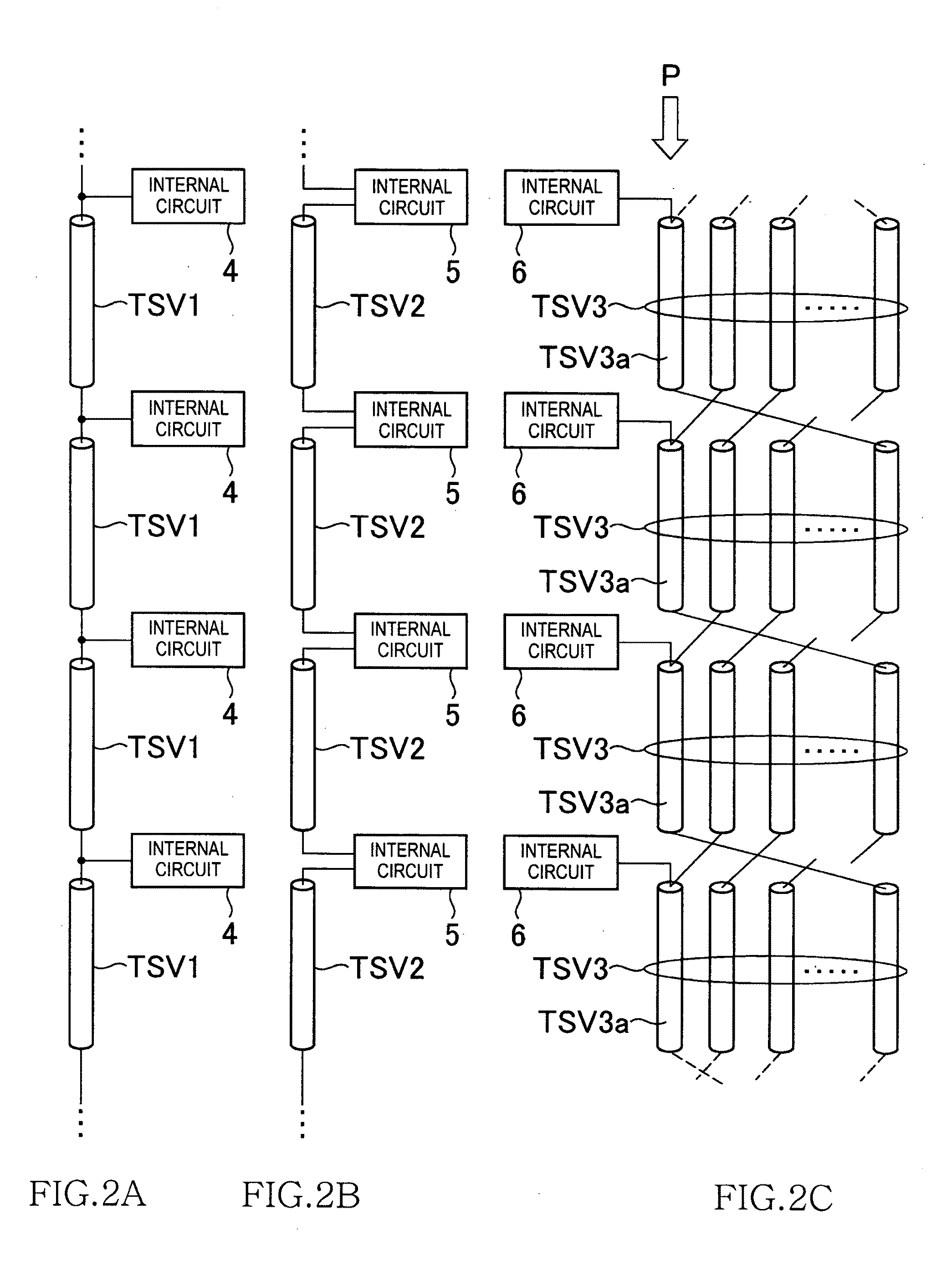
[0028]As shown in FIG. 1, the semiconductor device 10 according to this embodiment has the structure where 8 core chips CC0 to CC7 that have the same function and structure and are manufactured using the same manufacture mask, an interface chip IF that is manufactured using a manufacture mask different from that of the core chips and an interposer IP are laminated. The core chips CC0 to CC7 and the interface chip IF are semiconductor chips using a silicon substrate and are electrically connected to adjacent chips in a vertical direction through plural Through Silicon Vias (TSV) penetrating the silicon substrate. Meanwhile, the interposer IP is a circuit board that is made of a resin, and plur...


PUM

PropertyMeasurementUnit
Timeaaaaaaaaaa
Levelaaaaaaaaaa

Abstract

A semiconductor device includes a plurality of core chips and an interface chip stacked together. Each of the core chips and the interface chip includes plural through silicon vias that penetrate a semiconductor substrate and a bidirectional buffer circuit that drives the through silicon vias. The interface chip also includes a logic-level holding circuit that holds a logic level of the through silicon vias. The bidirectional buffer circuit includes an input buffer and an output buffer. The driving capability of a first inverter of the logic-level holding circuit is smaller than the driving capability of the output buffer of the bidirectional buffer circuit.

Description

BACKGROUND OF THE INVENTION[0001]1. Field of the Invention[0002]The present invention relates to a semiconductor device and an information processing system including the same. More particularly, the present invention relates to a semiconductor device that includes plural core chips and an interface chip to control the cores and an information processing system including the same.[0003]2. Description of the Related Art[0004]A memory capacity that is required in a semiconductor device such as a dynamic random access memory (DRAM) has increased every year. In recent years, a memory device that is called a multi-chip package where plural memory chips are laminated is suggested to satisfy the required memory capacity. However, since the memory chip used in the multi-chip package is a common memory chip capable of operating even though the memory chip is a single chip, a so-called front end unit that performs a function of an interface with an external device (for example, memory control...

Claims


Application Information

Patent Timeline
IPC IPC(8): H03K19/0175G01R31/28
CPCG11C5/02G11C5/04G11C29/12Y10T29/49004H03K19/0175H01L2224/16145G11C29/1201
Inventor KONDO, CHIKARA
Owner LONGITUDE LICENSING LTD
Why Eureka
Try Eureka