Eureka AIR delivers breakthrough ideas for toughest innovation challenges, trusted by R&D personnel around the world.

Multi-hole multi-angle drilling clamp

A multi-angle, fixture technology, applied in the direction of manufacturing tools, metal processing equipment, metal processing machinery parts, etc., can solve the problems of long assembly turnover cycle, unstable assembly fixture, slow production progress, etc., to improve processing efficiency and product qualification efficiency, reduce fixture turnover and preparation time, solve practical problems and improve the effect

Active Publication Date: 2016-01-27
SHENYANG AIRCRAFT CORP
View PDF5 Cites 1 Cited by
  • Summary
  • Abstract
  • Description
  • Claims
  • Application Information

AI Technical Summary

Problems solved by technology

In the process of processing, it is necessary to process multiple holes on the part. The previous processing method is to assemble two or more sets of drilling molds according to the spatial position of the hole, and process the holes in different spaces respectively, but it is used for processing space. The angled hole assembly fixture is very unstable. When the parts are mass-produced, it will have the following disadvantages. 1. The assembly fixture is unstable, the assembly turnover cycle is long, and it takes a long time to assemble, which is very inconvenient; 2. The parts need to be processed many times. Positioning installation takes a long time to prepare, the production progress is slow, and the position is likely to be inaccurate; 3. Multiple positioning, the product is likely to cause out-of-tolerance
The above shortcomings will directly cause delays in the production cycle of parts in mass production, and the decline in product quality.

Method used


Image

  • Multi-hole multi-angle drilling clamp
  • Multi-hole multi-angle drilling clamp
  • Multi-hole multi-angle drilling clamp

Examples


Embodiment Construction

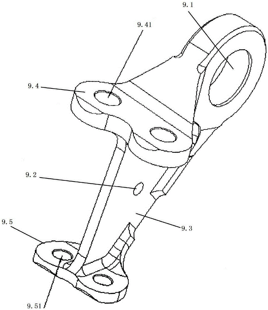
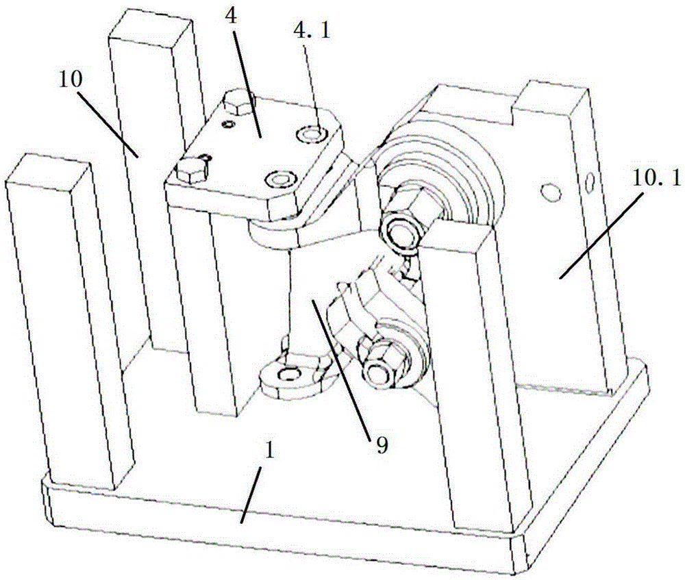
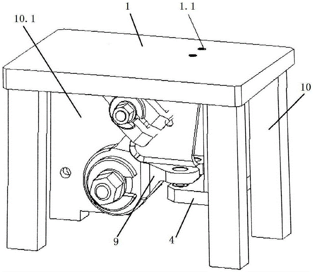
[0024] Such as Figure 1-5 As shown, a multi-hole multi-angle drilling fixture is used to clamp a part 9 with a hole in a spatial position. The part 9 has a mounting part I9.4 and a mounting part II9.5, and a mounting part I9.4 and a mounting part Ⅱ9.5 is arranged up and down on the part 9, the installation part I9.4 has a hole to be processed I9.41, the installation part II9.5 has a hole to be processed II9.51, and the processing fixture has a base 1, There are four pillars 10 around the base 1, a support block 11 is provided in the middle of the base 1, and a drill formwork 4 is provided on the support block 11. The installation part I9.4 and the installation part II9.5 are located between the base 1 and the drill formwork 4 Between, the lower surface of the drilling template 4 is parallel to the upper surface of the installation part I, and the drilling template 4 has a through hole I4.1 that matches the hole I9.41 to be processed; the upper surface of the base 1 and the T...


PUM


Abstract

The invention discloses a multi-hole multi-angle drilling clamp. A part to be machine comprises a first installing portion and a second installing portion which are distributed on the part in an up-down manner. The drilling clamp comprises a base, four supporting columns are arranged at the periphery of the base, a supporting block is arranged in the middle of the base, and a drill plate is arranged on the supporting block; the portion, to be machine, of the part is arranged between the base and the drill plate; the lower surface of the drill plate is parallel to the upper surface of the first installing portion, and a first through hole matched with a first hole to be machine is formed in the drill plate; the upper surface of the base is parallel to the lower surface of the second installing portion, and a second through hole matched with a second hole to be machine is formed in the base; and a column on the base (1) serves as a leaning plate, a locating shaft and a locating pin are arranged on the leaning plate, and the part can be fixedly installed on the leaning plate through the action of shaft holes on the locating shaft and the part and the action of pin holes on the locating pin and the part. A plurality of clamps can be combined into a set of dedicated clamp. Thus, the multi-hole multi-angle drilling clamp is convenient to use, the times for preparing and installing the part are reduced, and the locating accuracy is guaranteed.

Description

technical field [0001] The invention relates to a multi-hole multi-angle drilling fixture, which is used for processing multiple holes with spatial angles on a single part. Background technique [0002] Parts with complex shapes often appear on the aircraft. Due to assembly requirements, the parts themselves need holes with many spatial angles, such as figure 1 As shown, the material of the part is 30CrMnSiNi2A, a high-strength structural steel. The material has high toughness, is not easy to cut, and is difficult to process. It is widely used in the aerospace field. In the process of processing, it is necessary to process multiple holes on the part. The previous processing method is to assemble two or more sets of drilling molds according to the spatial position of the hole, and process the holes in different spaces respectively, but it is used for processing space. The angled hole assembly fixture is very unstable. When the parts are mass-produced, it will have the follow...

Claims


Application Information

Patent Timeline
IPC IPC(8): B23Q3/06B23B47/28
CPCB23B47/28B23Q3/062
Inventor 魏茹张永亮刘喆
Owner SHENYANG AIRCRAFT CORP
Why Eureka
Eureka Blog
Learn More