a wire connector

A wire splicer and splicing technology, applied in the field of wire splices and load-bearing splicing fittings, can solve the problem of not considering the tension bearing capacity of the terminal clamp, and achieve the effects of simple structure, enhanced friction, and good tension bearing capacity.

Active Publication Date: 2018-03-27
GUANGZHOU PANYU CABLE WORKS
View PDF10 Cites 0 Cited by
  • Summary
  • Abstract
  • Description
  • Claims
  • Application Information

AI Technical Summary

Problems solved by technology

From the above patent application and analysis of other existing technical solutions, it is found that these improvement solutions do not consider the tension bearing capacity of the terminal clamp. In actual use, the terminal clamp is easy to install and disassemble. If it is in some connection fields, it needs to be easy to install. and disassembly, and at the same time need to bear a certain tension, no matter what kind of existing connecting fittings are used, they cannot meet the requirements very well

Method used


Image

  • a wire connector
  • a wire connector
  • a wire connector

Examples


Embodiment 1

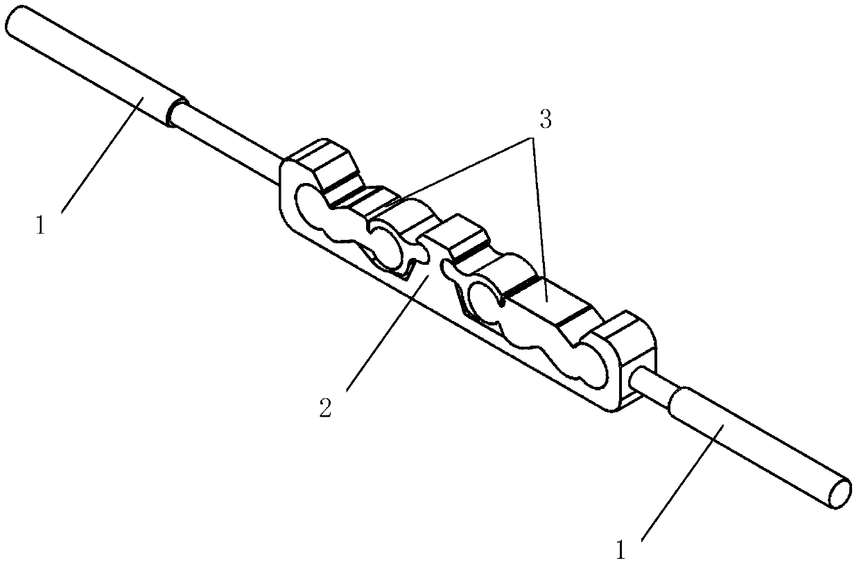
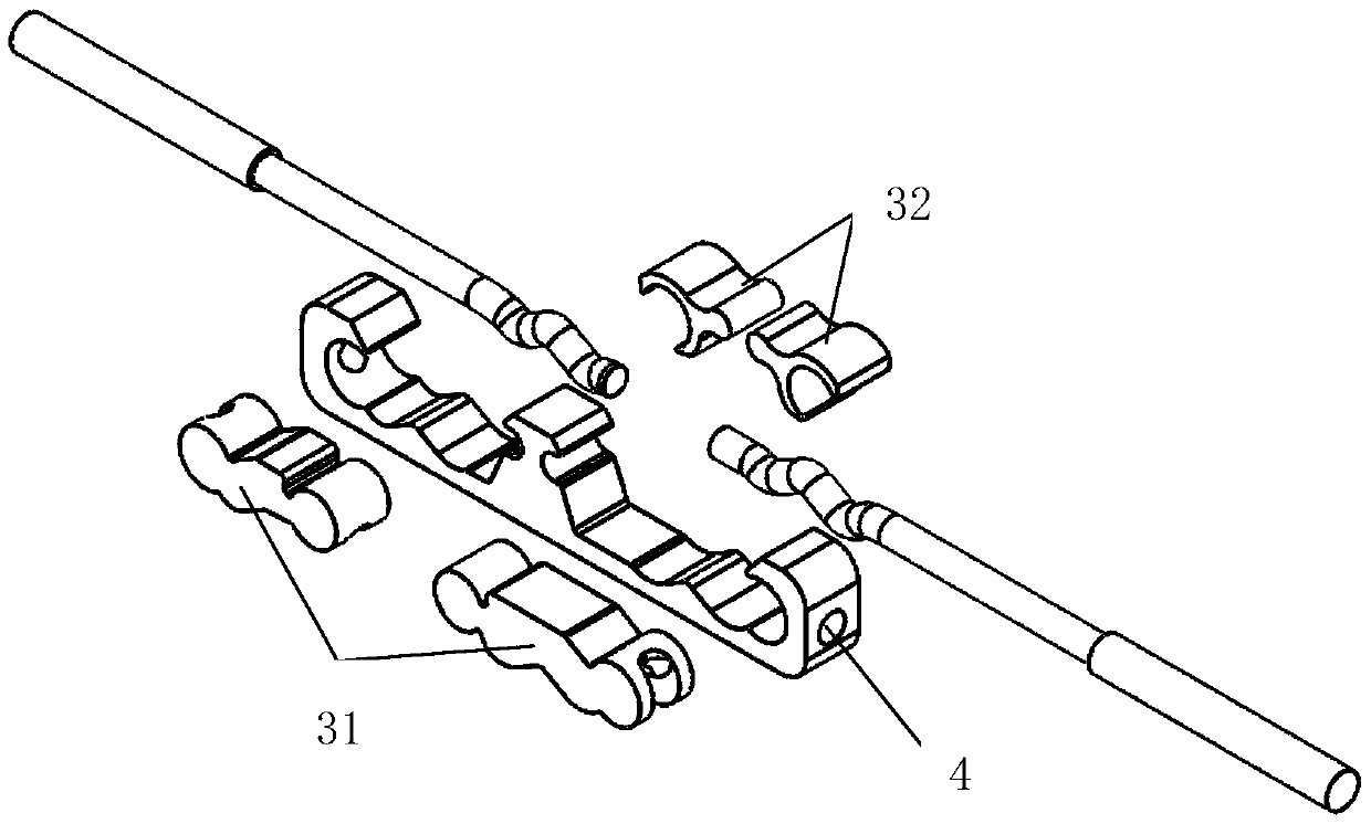
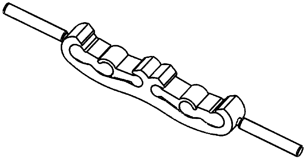
[0047] Such as figure 1 , 2 As shown, a wire connector includes a connector body 2 provided with at least one accommodating cavity 21 and a locking block 3 corresponding to each accommodating cavity, and is used for detachably connecting the connector body 2 and the lock The locking device of tight block 3; as Figure 7 , 8 As shown, the locking block 3 is assembled in its corresponding accommodating cavity 21; one surface of the accommodating cavity 21 is provided with a concave-convex creasing structure, and one surface of the corresponding locking block 3 is provided with The concave-convex crimping structure matched with it, and the two ends of the connector body 2 are provided with a wire hole 4, and the wire hole 4 is connected with the accommodating cavity 21 adjacent to it; when in use, the wire passes through the wire hole 4 Insert, set between the concave-convex crimping structure of the accommodating cavity 21 and the concave-convex crimping structure of the lock...

Embodiment 2

[0060] On the basis of the technical solution of the wire binding clip described in embodiment 1, the following improvements have been further made:

[0061] The accommodating cavity 21 is a "C-shaped" groove, or the body groove is an "O-shaped" groove. The locking device includes a locking screw 5 .

[0062] The accommodating cavity 21 is a "C-shaped" groove, and the connector body 2 and the locking block 3 are respectively provided with a first through hole and a second through hole, and the second through hole is located in one of the On the block or between two blocks, the first through hole and the second through hole are light holes, and the locking screw 5 passes through the first through hole and the second through hole to cooperate with a locking nut , and the detachable connection and locking of the connector body 2 and the locking block 3 can be realized, or one of the first through hole and the second through hole is a light hole, and one through hole can be conne...

Embodiment 3

[0069] On the basis of the technical solution of the wire clamp described in embodiments 1 and 2, the following improvements have been further made:

[0070] Such as Figure 14 As shown, the connector body 2 is provided with two accommodating cavities 21 arranged in series, and the wire holes 4 on both sides of the connector body 2 are located on the same axis; the connection between the two accommodating cavities 21 The connector body 2 is provided with a through hole 22, and the two accommodating cavities 21 and the through hole 22 are connected through another pair of wire holes 4 respectively; when in use, the wires are inserted from the wire holes 4 on both sides of the connector body 2 and run through the entire accommodating cavity twenty one.

[0071] Such as Figure 15 As shown, the through hole 22 is also provided with a crimping screw 23 in the vertical direction; when in use, one end of the two wires is arranged in the through hole 22, and a locking force is appl...


PUM


Abstract

The invention discloses a wire connector. The wire connector comprises connector bodies each provided with at least one accommodation cavity, locking blocks arranged to be corresponding to the accommodation cavities, and locking devices for detachable connection with the connector bodies and the locking blocks. The locking blocks are assembled in the corresponding accommodation cavities; one surface of each accommodation cavity is provided with a concave-convex pressing line structure, correspondingly, one surface of each locking block is provided with a matched concave-convex pressing line structure, the two ends of each connector body are each provided with a wire hole, and the wire holes penetrates through adjacent accommodation cavities. The wire connector provided by the invention has the advantages of simple structure, good electrical property, excellent tension bearing capability, convenient connection installation, flexible dismounting, high versatility, capability of self-locking, convenient unlocking and safe and stable connection.

Description

technical field [0001] The invention belongs to the field of wire connection, and in particular relates to a load-bearing connecting fitting: a wire connector. Background technique [0002] In the process of power transmission, the safety and stability of wire connection is very important. Generally, the connection of wires is realized by connecting fittings. The connecting fittings are used for the wires of overhead power lines or the two terminals of lightning protection wires to bear all the tension of the wires and lightning protection wires or not. It is also used for the repair of broken strands of wires and lightning conductors. At the same time, as a conductor, the following conditions must be met after wiring: the mechanical strength of the connection point should not be less than 95% of the calculated breaking force of the connected wires. The resistance between two points at the joint should not be greater than the resistance of the wire of the same length, and th...

Claims


Application Information

Patent Timeline
Patent Type & Authority Patents(China)
IPC IPC(8): H02G7/02H02G7/05
Inventor 胡超强尤占山安向阳覃丹王利江卢广业张仕欢申常伟陈雪儿何平
Owner GUANGZHOU PANYU CABLE WORKS
Why Eureka
Try Eureka