Electromyograph for the detection of electromyographic signals on moving subjects

Inactive Publication Date: 2006-12-21
COMETA S A S DI ALBERTO DELLACORNA& C
View PDF5 Cites 12 Cited by
  • Summary
  • Abstract
  • Description
  • Claims
  • Application Information

AI Technical Summary

Benefits of technology

[0020] According to a further feature of the invention, the basic unit (U) comprises a radio-transmitter capable of sending digital signals to the sensors (S, F) for controlling the power consumption of the battery (5), through the configuration of said sensors (S, F) into four different activation states comprising: a low-consumption SLEEP state, a transient synchronisation SYNC state, a waiting READY state, and a data acquisition OPERATE state.

Problems solved by technology

As said above, the electromyograph disclosed in U.S. Pat. No. 6,643,541 has not been effectively introduced in the market yet, and this is probably due to the fact that, as described in the patent, some important implementations appear to be lacking which are essential to allow the practical application thereof in the field of dynamic electromyography.

Method used


Image

  • Electromyograph for the detection of electromyographic signals on moving subjects
  • Electromyograph for the detection of electromyographic signals on moving subjects
  • Electromyograph for the detection of electromyographic signals on moving subjects

Examples


Embodiment Construction

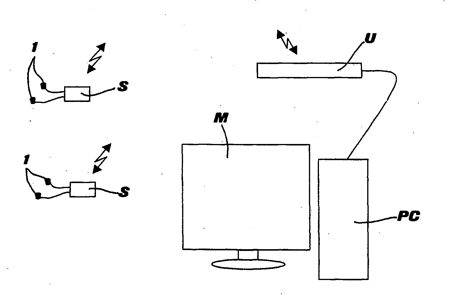
[0030] As shown in FIG. 1, the electromyograph according to the present invention comprises a fixed basic unit U and one or more sets of wireless sensors S, each set preferably consisting of eight differential sensors. Basic unit U is operated both manually and by a main (host) processor PC, connected with unit U through a USB interface and equipped with a screen M for the immediate display of data and information. Through a suitable software installed on the processor PC, it is then possible to programme the various functions of unit U and of sensors S.

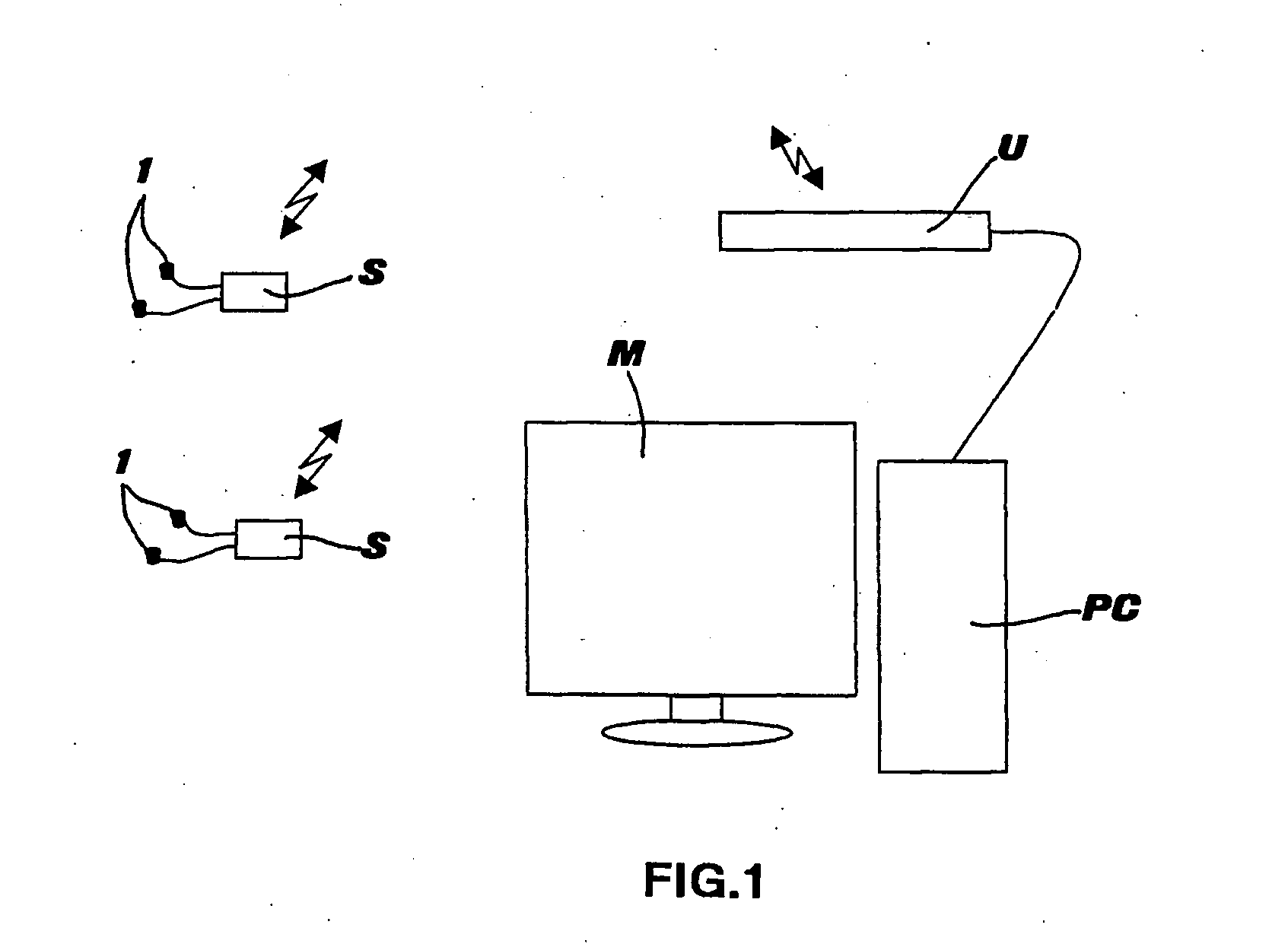
[0031] In FIG. 2 it can be appreciated that basic unit U comprises a 2.4 GHz receiver-transmitter module RF with the relevant antenna, a microprocessor MCU, a digital / analogical multiple converter D / A connected with an analogical output, a receiver switch CR, and finally a USB interface for connection with the processor PC. Unit U is equipped with a universal, 90-240 Vac power supply, for direct connection to an outlet. The system u...


PUM


Abstract

An apparatus for the detection of electromyographic signals in a moving subject includes signal sensors (S) and movement sensors (F) applied to the subject, each including elements (1) for the analogical picking-up of signals, an amplifier (A) of the detected analogical signals, an analogical/digital converter (A/D) of the amplified signals, a low-consumption microcontroller (2) with independent power supply, for controlling the flow of digital signals to a radio-transmitter (3) apt to sequentially issue the digital signals to a basic unit (U). The basic unit (U) includes a radio-receiver apt to receive the signals coming from the signal sensors (S) and movement sensors (F), a digital/analogical converter, a microcontroller (MCU) and a USB-standard, serial interface unit, the unit thereby being apt to transmit the signals, in digital and/or analogical format, to external devices for signal interpretation and display.

Description

BACKGROUND OF THE INVENTION [0001] 1. Field of the Invention [0002] The present invention refers to an improved electromyograph, particularly suited to detect electromyographic signals on moving objects, such as in particular a human or another animal. [0003] As known, electromyographs are devices which allow to detect the electric activity of the muscles. This detection action may be carried out in static conditions, i.e. with the patient holding still providing to the voluntary contraction of the muscle or muscles of interest only, or in dynamic conditions, i.e. while the patient walks or performs specific trunk, arm or head movements, for the purpose of studying the patient's muscle response during motor activities simulating the ones that the patient performs in ordinary life. [0004] Dynamic electromyography is an extremely interesting and innovative medical technology, since it allows to assess muscle function in actual working conditions and it consequently enables the physici...

Claims


Application Information

Patent Timeline
Patent Type & Authority Applications(United States)
IPC IPC(8): A61B5/04
CPCA61B5/0002A61B5/1118A61B5/0488A61B5/389
Inventor DELLACORNA, ALBERTO
Owner COMETA S A S DI ALBERTO DELLACORNA& C
Why Eureka
Try Eureka