Auto-eject gun-lock device with ring-mounted key

a gun-lock device and key-mounted technology, applied in the direction of weapons, weapon components, safety arrangements, etc., can solve the problems of insufficient barrier, inflicting damage to both, and failure of the chamber-engaging arrangemen

Inactive Publication Date: 2006-12-28
HA DON DONGCHO
View PDF13 Cites 9 Cited by
  • Summary
  • Abstract
  • Description
  • Claims
  • Application Information

AI Technical Summary

Benefits of technology

[0014] Some user may prefer to wear the ring such that the key is on the palm side of the hand. If worn this way, all of the user's fingers will be better positioned to cradle the exterior of the gun barrel as the key is being inserted, so even greater degree of tactile sense feedback may be afforded to further improve the speed at which the key is engaged with the lock mechanism. The key may be worn on any finger, in any orientation, and on either of user's hands depending on the individual's preference and on his instinctive movements of the hands and arms, so as long as it allows speedy and effective key-to-lock engagement at all times.
[0018] The tumbler cylinder of the present invention fits within the head of the lock subassembly and is allowed to be rotated a partial turn when the correct key is inserted. The limits of the turn are precisely governed by the mechanical stops at both ends. The tumbler cylinder is spring loaded to return to and maintained at its normally locked position. On the frontal contacting surfaces of the tumbler cylinder and the key are an asymmetrical recess feature and a matching projection feature, respectively, which are designed to help guide the key into correct insertion into the lock arrangement. The asymmetrical shape of these matching features ensure that the key is inserted only when it is properly aligned in correct angular relationship with respect to the tumbler cylinder. Further, the lock arrangement of the present invention operates on a concept similar to that of existing variety of lock-pin tumbler design commonly used in many padlocks and door-lock devices, except that the lock-pins of the present invention are disposed parallel to and in a circular formation about the axis of rotation of the tumbler cylinder, whereas in an existing variety, the lock-pins are disposed in a row, perpendicular to the axis of rotation of the tumbler cylinder. The parallel-axes arrangement affords the present invention an advantage, as such arrangement reserves a compact physical packaging possibility. For example, for a gun-lock device for large-bore handguns of such calibers as .40 S&W and .45 ACP, the lock pins may be arranged in a circular formation of such diameter which may be housed within the portion of the tubular assembly that fit within the bore of the gun barrel. It will then leave only a small portion of the gun-lock device to remain extending outside of the gun barrel. For smaller caliber handguns, of calibers such as the 38 special, .357 Magnum, .380 ACP, and 9 mm, the lock pins may be packaged within that exposed portion of the tubular assembly which remain extending outside of the barrel. However, because the parallel-axes lock-pin arrangement requires a housing of much smaller diameter than those of conventional arrangements based on the lock-pin tumbler or the combination disks designs, the overall physical size of that portion of the present invention which remain exposed outside of the gun barrel may be significantly less than those of the prior art examples. Such small size makes it possible for the present invention to be used in combination with a handgun which is worn in a holster, without causing a snag or an impeded motion during withdrawing of the handgun.
[0020] As briefly described above, the gun-lock device of the present invention provides many improvements and benefits over the prior art. With chamber plug member placed in the firing chamber, the tubular assembly is inserted through the gun barrel and only with a slight push inward of the chamber plug member made into the locked configuration without any additional input required by the gun-owner. To unlock, the ring finger of the gun-owner on which the key is worn is brought toward the head of the lock subassembly and guided only by the gun-owner's tactile senses the key may be correctly inserted into the tumbler cylinder. A simple twisting of the key unlocks the device and the tubular assembly immediately auto-ejects out from the gun barrel. The firearm is then ready to fire, in case of a revolver type gun, or immediately subsequent to cycling of the action, in case of a semi-automatic type gun. The ease and speed at which the present invention operates during both the lock and unlock operations coupled with its compact physical size provides a realistic option for the gun-owner to maintain his handgun locked at all times, including those times when the gun is carried in a holster worn by the gun-owner. The following illustrative drawings and detailed description make the foregoing and other objects, features, and advantages of the invention more apparent.

Problems solved by technology

Because of the small difference between the bore and the chamber diameters of most modern gun designs, the width of this edge is very narrow and thus cannot sufficiently provide as a barrier means to prevent the gun-lock device from being pulled out from the chamber through the bore of the firearm.
With force exerted during an unauthorized removal attempt, the parts of the gun-lock device engaging with the narrow edge, the narrow edge itself, and / or the body of the lock-device may breakdown and cause the chamber-engaging arrangement to fail.
A forced tamper attempt would likely to inflict damage to both the handgun and the prior art gun-lock device, and ultimately may result in an inadvertent removal of the device from the handgun.

Method used


Image

  • Auto-eject gun-lock device with ring-mounted key
  • Auto-eject gun-lock device with ring-mounted key
  • Auto-eject gun-lock device with ring-mounted key

Examples


Embodiment Construction

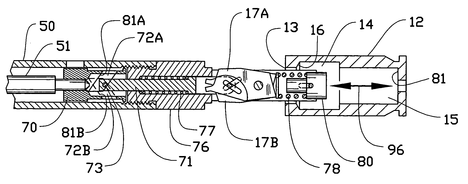
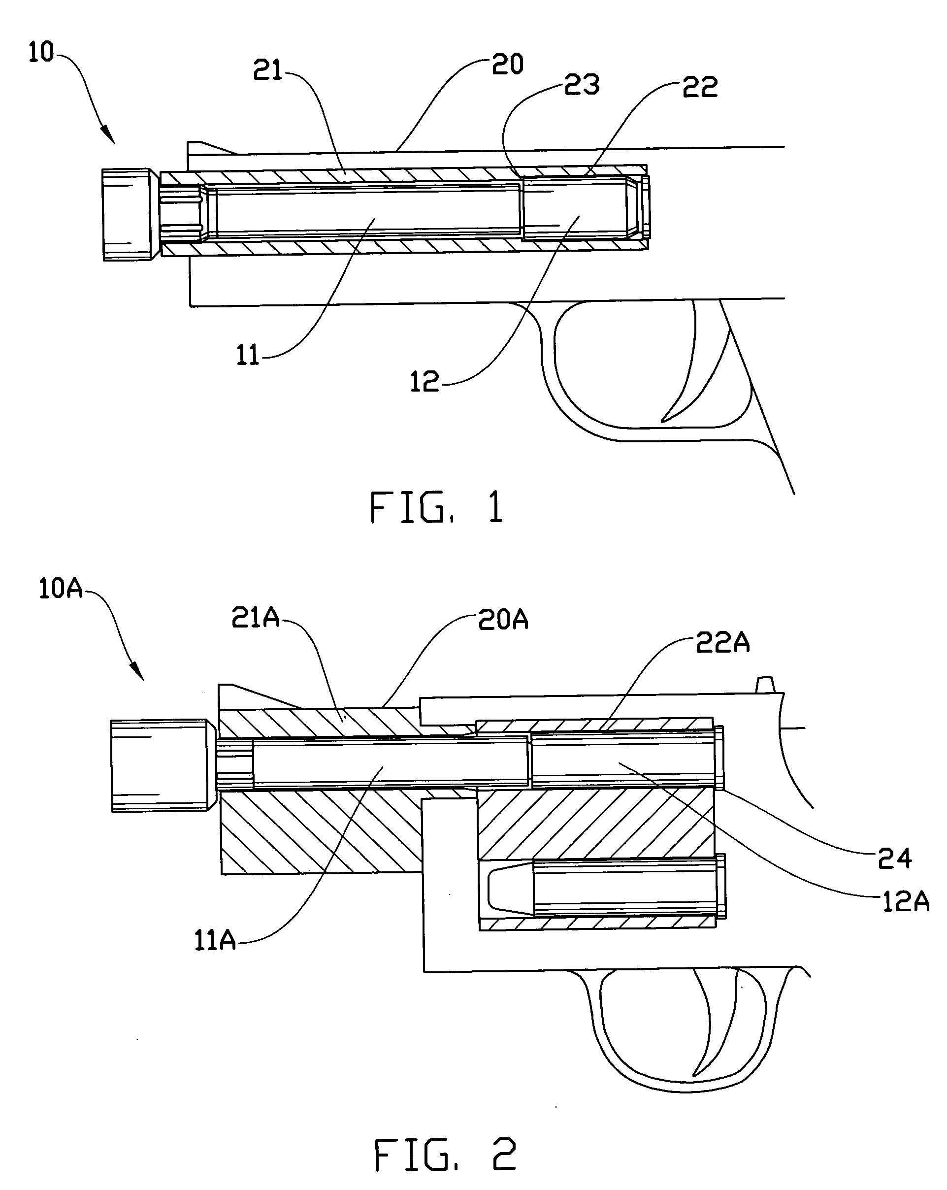
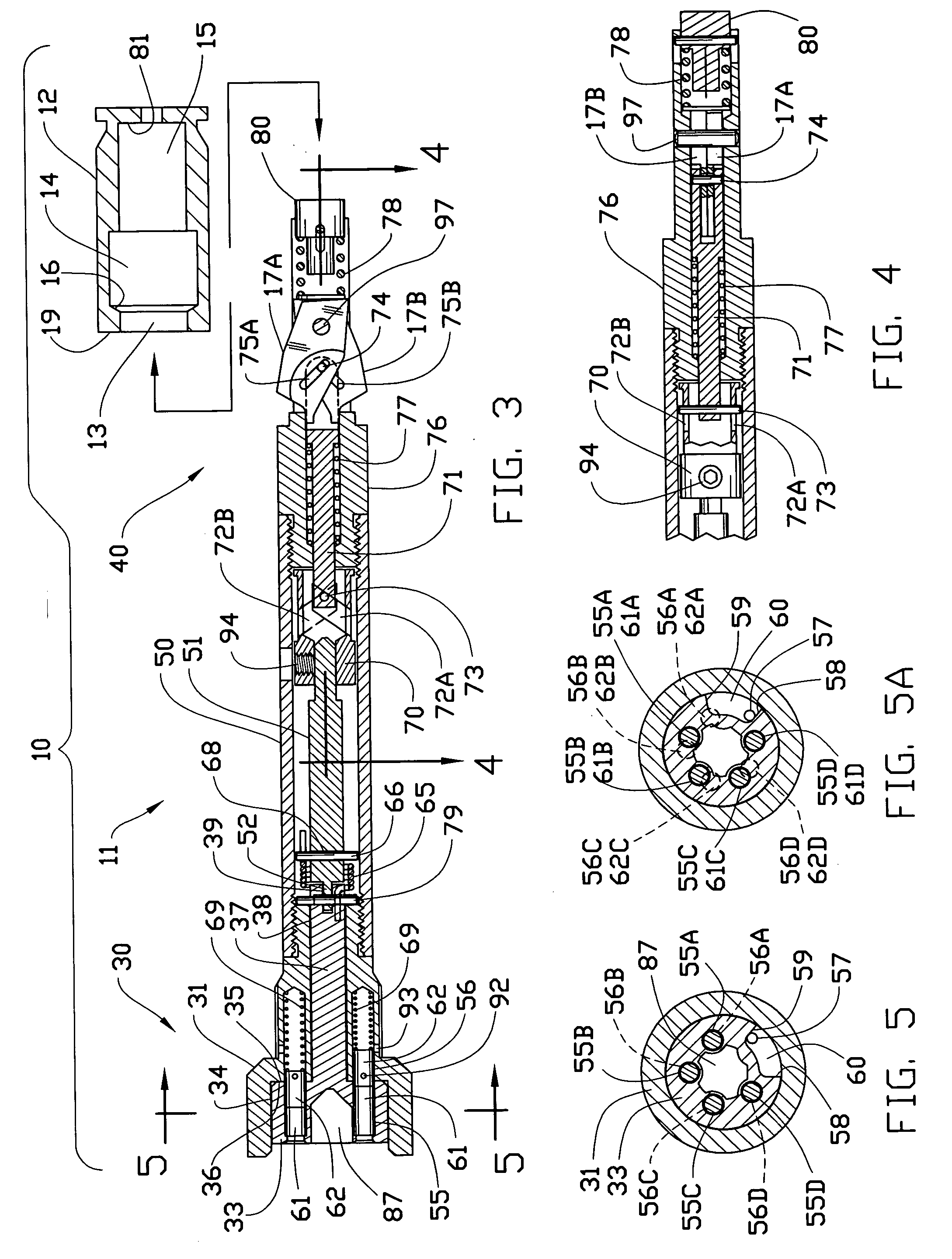
[0038]FIGS. 1-16 of the drawings illustrate various aspects of a gun-lock device 10 constructed according to the invention. Although the following discussions may reference specific features and functions of a large-bore semi-automatic handgun, the inventive concepts disclosed and claimed are not restricted to such. A gun-lock device constructed according to the invention may be configured for use with any handgun or a long gun of semi-automatic, revolver, or of other action type of any caliber size, so as long as the firearm has a barrel with a bore and a chamber.

[0039] The gun-lock device 10 of FIG. 1 includes a tubular assembly 11 which is inserted from the muzzle end of the barrel 21 of the firearm 20 and a chamber plug member 12 which is inserted into the chamber 22 from the breach end of a semi-automatic handgun of such caliber as .40 S&W. The gun-lock device 10A of FIG. 2 is a variation adapted to work with a revolver of such caliber as .357 Magnum, wherein a tubular assembl...


PUM


Abstract

A gun-lock device includes a tubular assembly that fits within the bore and a chamber plug member that fits within the chamber of a firearm. The tubular assembly is partially received into the chamber plug member, wherein spring-loaded expandable arrangement at the end thereof engages with the recess within the chamber plug member to lock the tubular assembly within the barrel. The lock subassembly includes a tumbler cylinder arranged to rotate about the longitudinal axis of the tubular assembly and a set of lock-pins which are disposed parallel to, and in a circular formation about, the longitudinal axis of the tumbler cylinder. The resulting overall arrangement yields a compactly packaged gun-lock device suitable for use in combination with a holster-worn firearm, and the key, with such small size and ornate shape, suitable for being mounted on a ring to be worn by the user at all times. A spring loaded plunger mechanism enhances the speed and ease of operation by adding a self-eject feature to the device.

Description

REFERENCES CITED (REFERENCED WITHIN THE SPECIFICATION) [0001]43983668 / 1983Wernicki45120994 / 1985Mathew52896533 / 1994Szebeni et al.547599412 / 1995Briley, Jr. et al.54919182 / 1996Elmstedt56643589 / 1997Haber et al.58602411 / 1999Waters65609105 / 2003McLarenCROSS-REFERENCE TO RELATED APPLICATIONS [0002] Not applicable. BACKGROUND OF THE INVENTION [0003] 1. Technical Field [0004] This invention relates to a safety gun-lock device for firearms, and more particularly for handguns for preventing unauthorized use, yet allow speedy unlocking and removal of the gun-lock device for authorized use of the firearm. [0005] 2. Description of the Related Art [0006] Several of existing gun-lock devices are made in the form of a “barrel lock”, wherein a tubular body portion of the gun-lock device is inserted into the barrel and the firing chamber portions of the firearm and is locked in position to render the firearm inoperative until such device is removed. This type of device generally incorporates a chamber-...

Claims


Application Information

Patent Timeline
Patent Type & Authority Applications(United States)
IPC IPC(8): F41A17/00
CPCF41A17/44
Inventor HA, DON DONGCHO
Owner HA DON DONGCHO
Why Eureka
Try Eureka