Resilient nasal intubation tube supporter

a technology of intubation tube and supporter, which is applied in the direction of intravenous devices, catheters, infusion needles, etc., can solve the problems of unobtrusive use and operation, and the entire intubation tube supporter is extremely lightweight and easy to carry around, and achieves the effect of rapid adjustment and quick adjustmen

Inactive Publication Date: 2006-12-28
HELSEL PAULA ANN
View PDF14 Cites 35 Cited by
  • Summary
  • Abstract
  • Description
  • Claims
  • Application Information

AI Technical Summary

Benefits of technology

[0017] The novel intubation tube holder may also be rapidly adjusted in the operating room environment for height along the horizontal axis by perforating or by joining two smaller V-shaped sections, the top one having the nasal intubation adhesive covered groove or a semi circular adhesive opening and the bottom one having the substantially flat adhesive coated surface. In embodiments where height adjustability is provided both sides of the perforated or layered sections preferably include an adhesive and where two separate sections are employed as opposed to perforations a double-backed protective release strip may be employed to hold both sections together. Separation of the two sections may then be made in the operation room rapidly and efficiently to accommodate differences in height which had heretofore been accomplished by increasing or decreasing the number of folds in the pad or towel.
[0018] Vertical and horizontal adjustability is accommodated by a combination of perforations and adhesive backing with a protective release strip holding both adhesive backed sections together. In the preferred embodiment of vertical and horizontal adjustability vertical adjustability is achieved by perforations disposed vertical to the horizontal plane of the adhesive coated based of the novel intubation tube holder. Horizontal adjustability is achieved by holding the two V-shaped sections held together having an adhesive held together by a protective release strip having a matching perforation or by two laterally adjacent release strips on either side or bridging the perforation. In this manner the length of the novel intubation tube supporter may be quickly separated by the vertical perforations to accommodate different sized foreheads and the thickness may be quickly adjusted to desired height requirements.

Problems solved by technology

The entire intubation tube supporter is extremely lightweight and unobtrusive in use and operation.

Method used


Image

  • Resilient nasal intubation tube supporter
  • Resilient nasal intubation tube supporter
  • Resilient nasal intubation tube supporter

Examples


Embodiment Construction

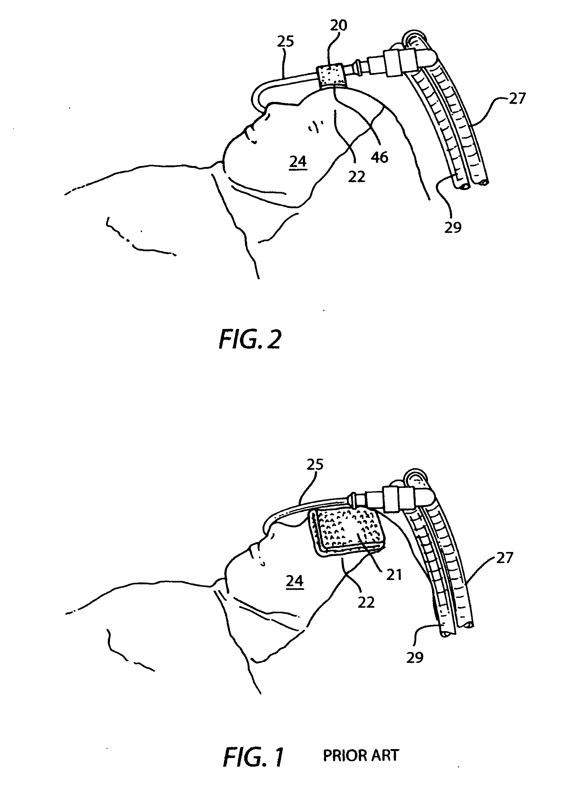
[0032] Prior art FIG. 1 illustrates the best known prior art currently employed in operating rooms for supporting nasal intubation tubes. As heretofore described the prior art employs a towel or pad 21 folded to provide the desired length, width and height to support a nasal intubation tube 25 along with the anesthesia breathing circuits having tubes 27, 29 that are connected to the nasal intubation tube 25. Towel or pad 21 is typically taped to the forehead 22 of the patient or around the patient's head or hair.

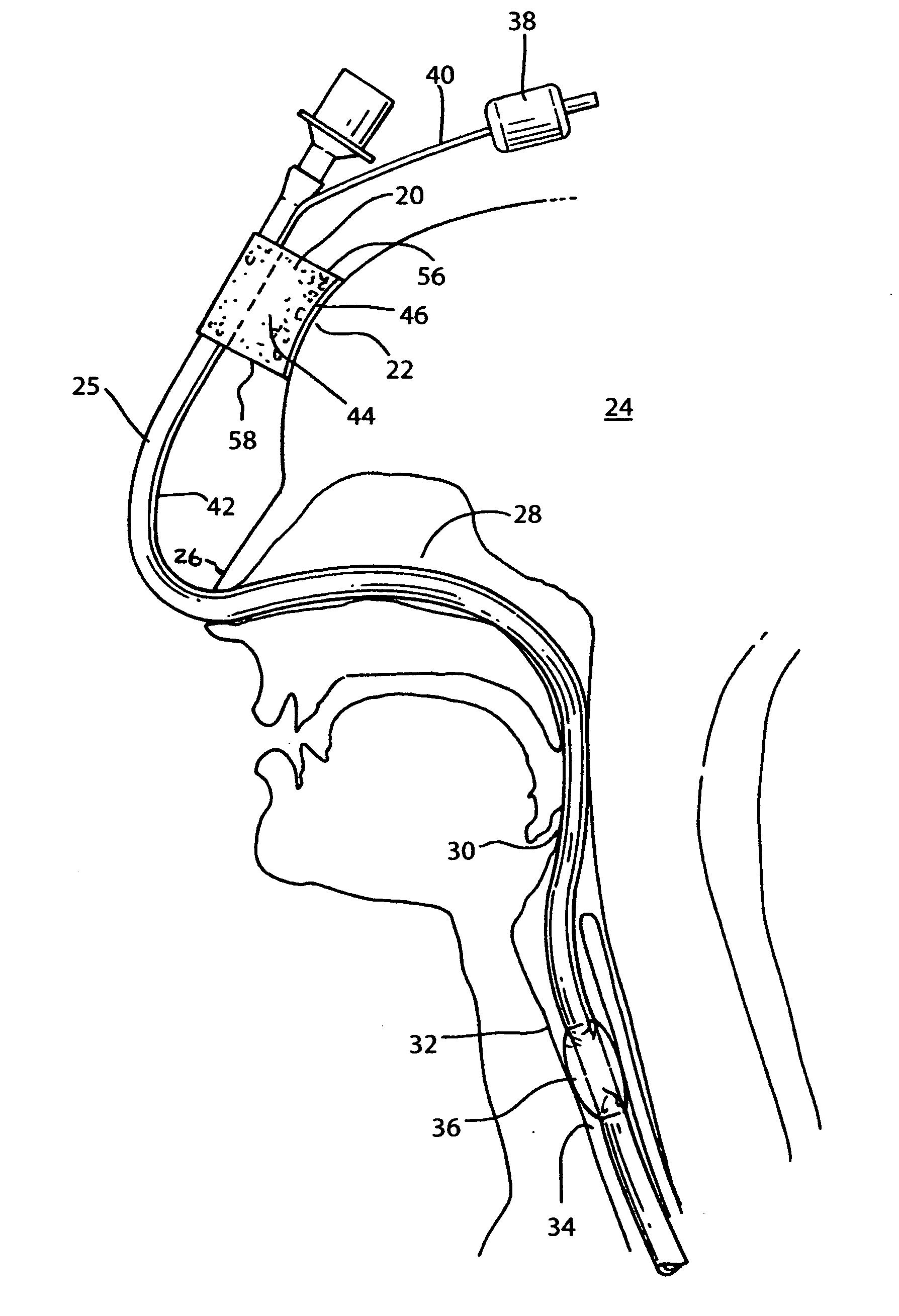
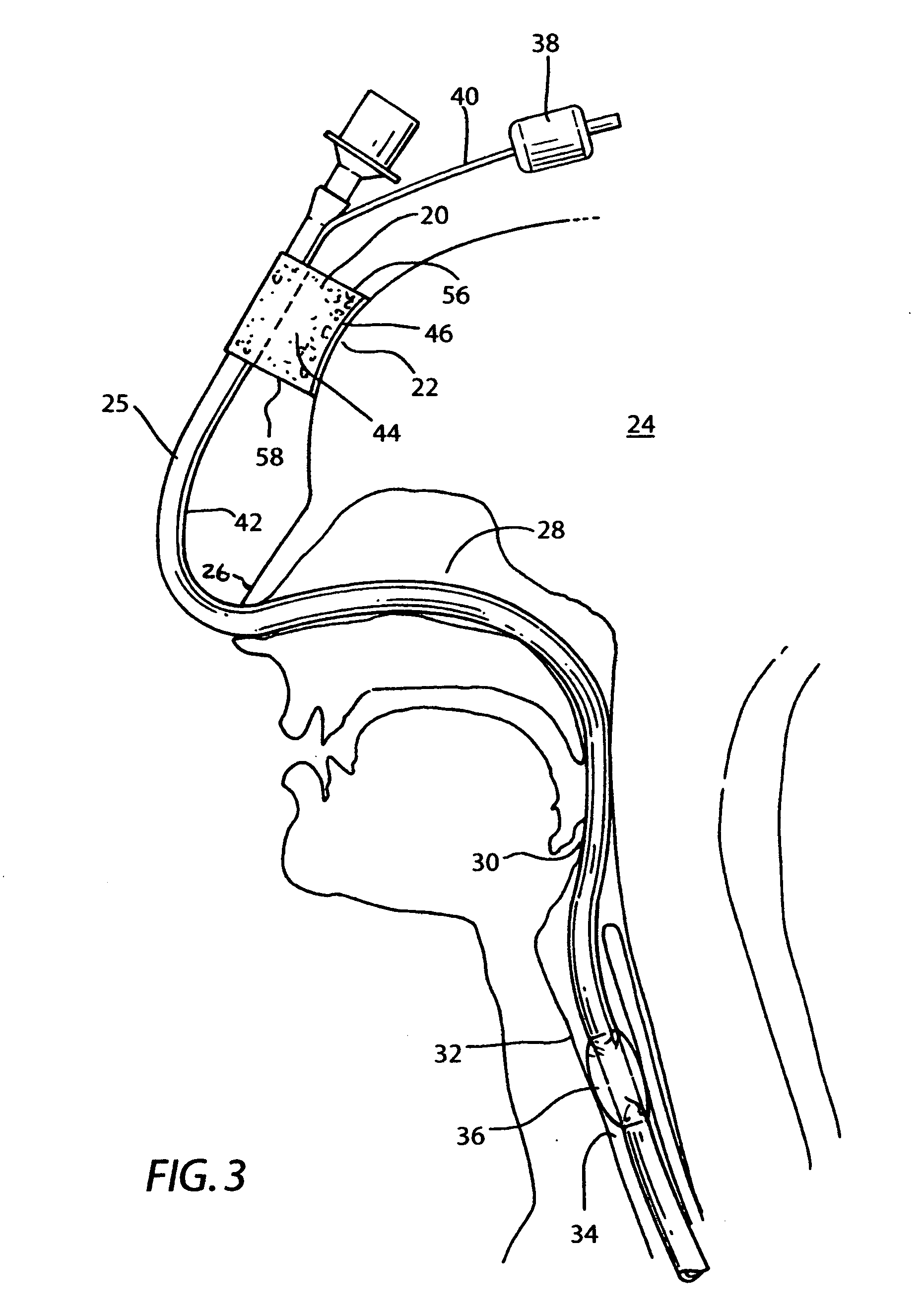
[0033] Referring now to FIG. 2, 3, 4 and 7 the novel intubation tube holder 20 constructed in accordance with the best mode and preferred embodiment is illustrated. Nasal intubation tube holder is designed to fix the position of the sinusoidal shaped nasal intubation tube 25 onto the forehead 22 of patient 24 at an elevation sufficient to accommodate the sinusoidal shaped tube which extends through nose 26 into the nasal septum 28 past the epiglottis 30 into the trachea 32 ...


PUM


Abstract

A resilient nasal intubation tube supporter is provided having an adhesive coated base and a nasal intubation tube groove having an adhesive layer separated by a resilient foam body for anchoring a sinusoidal shaped nasal intubation tube in place for surgical procedures. The invention includes provision for length and height adjustment of the novel intubation tube holder. The novel intubation tube holder provides a cushioned pliantly resilient support for nasal intubation tubes and provides support for conduits and hoses that need to be attached during surgical procedures.

Description

CROSS REFERENCE TO RELATED APPLICATIONS [0001] Not applicable. STATEMENT REGARDING FEDERALLY SPONSORED RESEARCH OR DEVELOPMENT [0002] Not applicable. INCORPORATION-BY-REFERENCE OF MATERIAL SUBMITTED ON COMPACT DISC [0003] Not applicable. REFERENCE TO A “MICROFICHE APPENDIX”[0004] Not applicable. BACKGROUND OF THE INVENTION [0005] 1. Field of the Invention [0006] The invention relates to a conduit support device used for facial surgery such as oral maxillary surgery under general anesthesia. More particularly the invention pertains to a device for resiliently and detachably anchoring a nasal intubation tube during major dental and medical surgery requiring access to the oral cavity under anesthesia. [0007] 2. Description of the Related Art Including in the U.S. Information Disclosed Under 37 CFR 1.97 and 1.98 [0008] The best known prior art in use for resiliently and detachably supporting nasal intubation tubes, which are known as nasal RAE and nasal tubes is illustrated in Prior Art...

Claims


Application Information

Patent Timeline
Patent Type & Authority Applications(United States)
IPC IPC(8): A62B9/06A61M5/32
CPCA61M2025/0226A61M25/02
Inventor HELSEL, PAULA ANN
Owner HELSEL PAULA ANN
Why Eureka
Try Eureka