Heat exchange element and heat exchanger produced therewith

a technology of heat exchange element and heat exchanger, which is applied in the direction of tubular element, lighting and heating apparatus, stationary conduit assembly, etc., can solve the problems of inability to heat transfer, small heat exchange output, and disruption of forming boundary layers, etc., and achieves enhanced heat exchange output (power) and reduced pressure loss

Inactive Publication Date: 2006-12-28
AUTOKUHLER GMBH & CO KG
View PDF5 Cites 46 Cited by
  • Summary
  • Abstract
  • Description
  • Claims
  • Application Information

AI Technical Summary

Benefits of technology

[0006] It is an object of the present invention to design the heat exchange element described a

Problems solved by technology

The formation of the boundary layers has the result that the wall surfaces which are present are only incompletely usable for heat transfer and that the achievable heat exchange outputs are small.
As a result, the parts of the fluid flows close to the walls are divided repeatedly with formation of local turbulences and the otherwise forming boundary layers are disrupted and destroyed.
On the one hand they are able not only to deflect the parts of the flow close to the walls in the direction of the core zones and consequently to increase the heat exchange output but also to reduce the flow cross-sections and consequently to lead to an undesired increase in the pressure losses occurring along the flow channels.
On the other hand, embossings of the described type can h

Method used


Image

  • Heat exchange element and heat exchanger produced therewith
  • Heat exchange element and heat exchanger produced therewith
  • Heat exchange element and heat exchanger produced therewith

Examples


Embodiment Construction

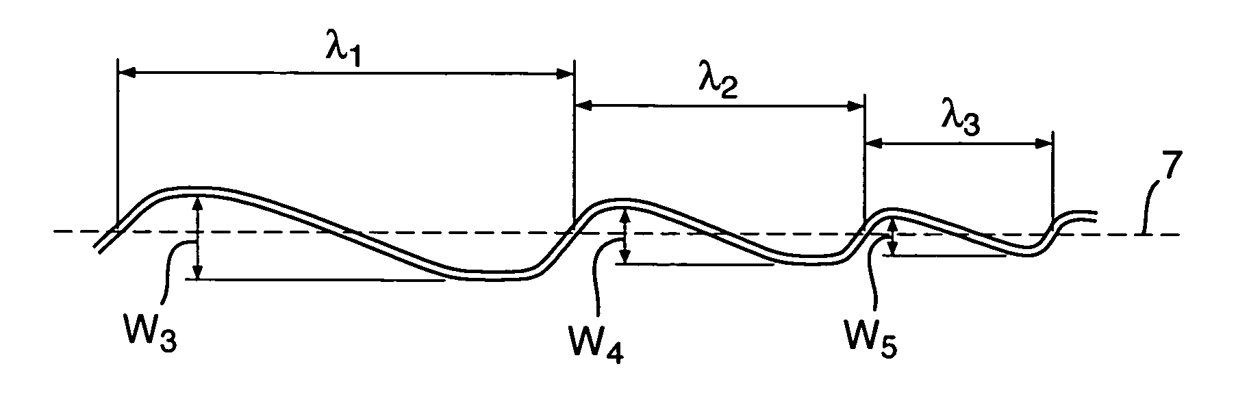
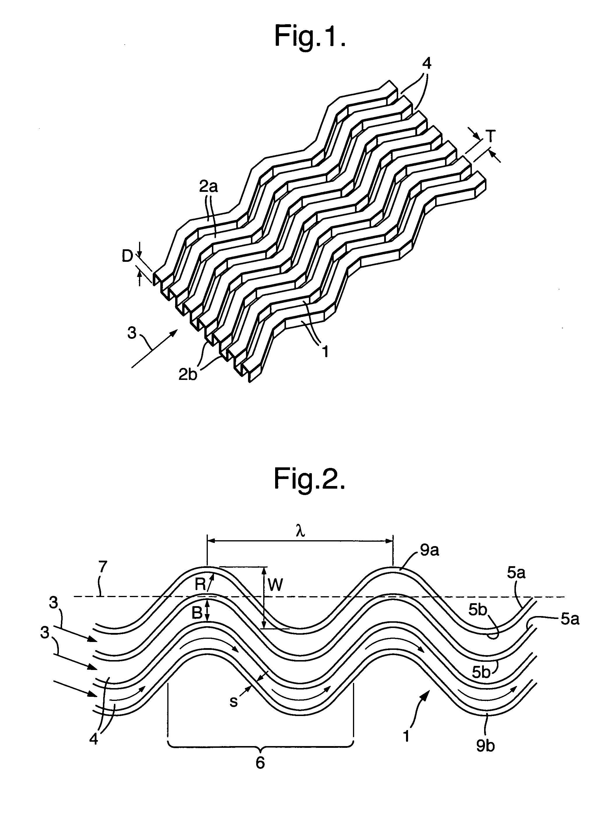
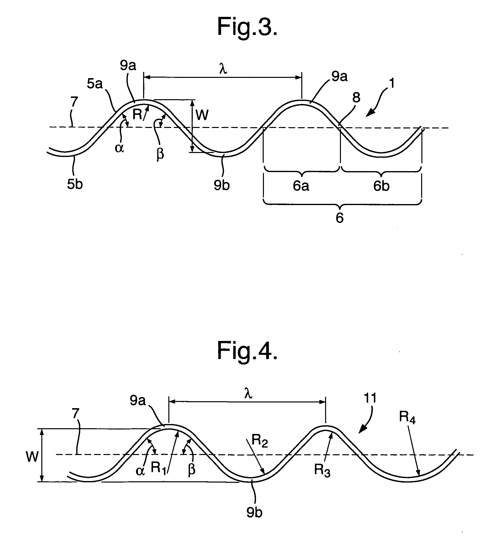
[0021]FIG. 1 to 3 show a heat exchange element according to the invention and according to an embodiment deemed to be the best one up to now. The heat exchange element comprises a plurality of adjacent, heat-transferring walls 1 which are preferably disposed parallel to each other. The walls 1 are formed by thin plates which have a height D (FIG. 1) and a thickness S (FIG. 2) and are connected to each other in a meandering shape at their upper and lower longitudinal edges in FIG. 1 by upper and lower, likewise plate-shaped connecting portions 2a, 2b. In a longitudinal direction of the heat exchange element indicated by arrows 3, a plurality of adjacent flow channels 4 for a fluid, which have U-shaped cross-sections, is consequently produced, these flow channels 4 respectively being delimited by two adjacent walls 1 and, in addition in FIG. 1, alternately by an upper or lower connecting portion 2a, 2b.

[0022] The flow channels 4 are open at their front and rear ends in the longitudin...


PUM


Abstract

A heat exchange element is described having adjacent, heat-transferring, smooth walls (1) which, between each other, delimit flow channels (4) with preselected channel widths (B) for at least one fluid and are provided with undulations (6) which protrude on both sides and transversely relative to imaginary central planes (7), said undulations having preselected wavelengths (λ) as well as apexes (9a, 9b) with radii of curvature (R) and apex spacings (W) measured transversely relative to the central planes (7). According to the invention inequalities 0.1≦B/W≦0.55 and R≧1.2 B apply at least partially to ratios of channel width (B)/apex spacing (W) and channel width (B)/radius of curvature (R) (FIG. 2).

Description

FIELD OF THE INVENTION [0001] The invention relates to a heat exchange element having adjacent, heat-transferring, smooth walls which, between each other, delimit flow channels with preselected channel widths for at least one fluid and are provided with undulations which protrude on both sides and transversely relative to imaginary central planes, said undulations having preselected wavelengths and apexes with radii of curvature and apex spacings measured transversely relative to the central planes. The invention also relates to a heat exchanger provided with such a heat exchange element. BACKGROUND OF THE INVENTION [0002] Heat exchange elements having adjacent, smooth walls which delimit, between each other, flow channels are, according to the purpose of use, components of pipe, plate or ribbed heat exchangers and / or are configured as fin arrangements or lamellae (corrugated ribs). They are used e.g. in automotive vehicles, compressors, washer-dryers, air-conditioning and refrigera...

Claims


Application Information

Patent Timeline
IPC IPC(8): F28D1/02
CPCF28D9/0062F28D2021/0029F28F3/046F28F3/02F28F3/025F28F1/126F28F3/00
Inventor LEUSCHNER, JOERGKOZICA, MICHAEL
Owner AUTOKUHLER GMBH & CO KG
Why Eureka
Try Eureka