Weed puller

a weed killer and weed technology, applied in the field of weed killers, can solve problems such as unusable use or manufactur

Inactive Publication Date: 2006-12-28
BASEK CHARLES
View PDF25 Cites 11 Cited by
  • Summary
  • Abstract
  • Description
  • Claims
  • Application Information

AI Technical Summary

Benefits of technology

[0007] In one aspect, the invention provides a weed puller comprising a body having an upper end and a lower end and a reciprocating element able to move upwards or downwards relative to the ends of the body. A first blade is attached to or integral with the lower end of the body. A retainer attached to the body holds the intermediate portion of the second blade at a point, or within a longitudinal and lateral range of distances, relative to the body, but allows the second blade to pivot between open and closed positions relative to the first blade. When the reciprocating element is in a lower position, the second blade is held in, or allowed to pivot to, its open position. When the reciprocating element is in an upper position, the reciprocating element prevents an upper portion of the second blade from moving laterally towards the body and so holds the second blade in a closed position.
[0008] In another aspect, the invention provides a weed puller comprising a body having an upper end and a lower end. A first blade and a rotating blade are attached to the lower end of the body. The rotating blade may rotate between open and closed positions relative to the first blade and is biased towards the open position. A reciprocating element may move between lower and upper positions along the body and is biased towards the upper position. The reciprocating element, when in the upper position, prevents the rotating blade from moving from the closed position to the open position. The reciprocating element, when in the lower position, occupies a portion of the space between the lower ends of the blades. The rotating blade, when in the open position, prevents the reciprocating element from moving to the upper position.

Problems solved by technology

A weed puller such as this has various attributes that make it undesirable to use or manufacture.

Method used


Image

  • Weed puller
  • Weed puller
  • Weed puller

Examples


Embodiment Construction

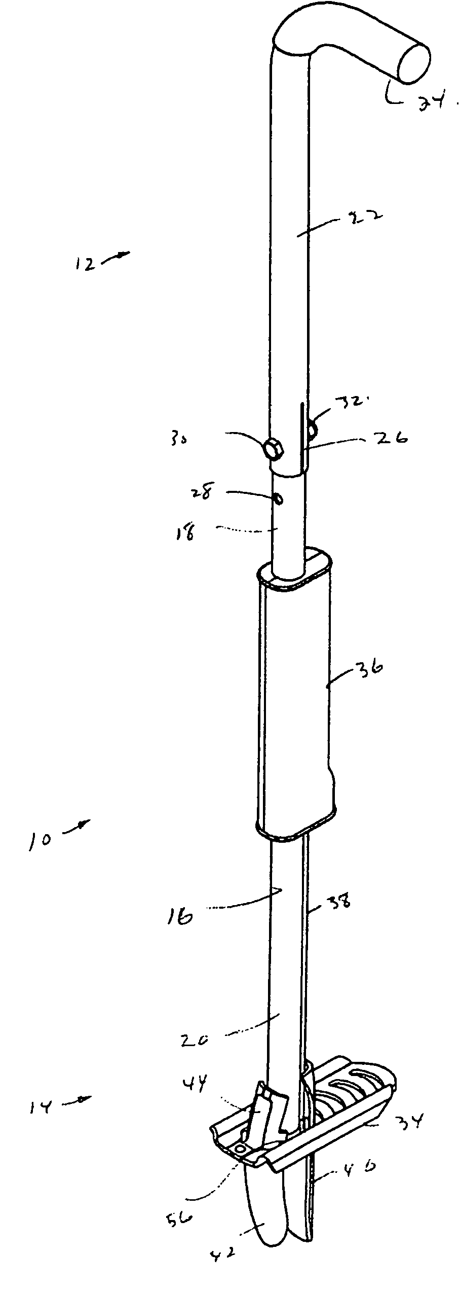
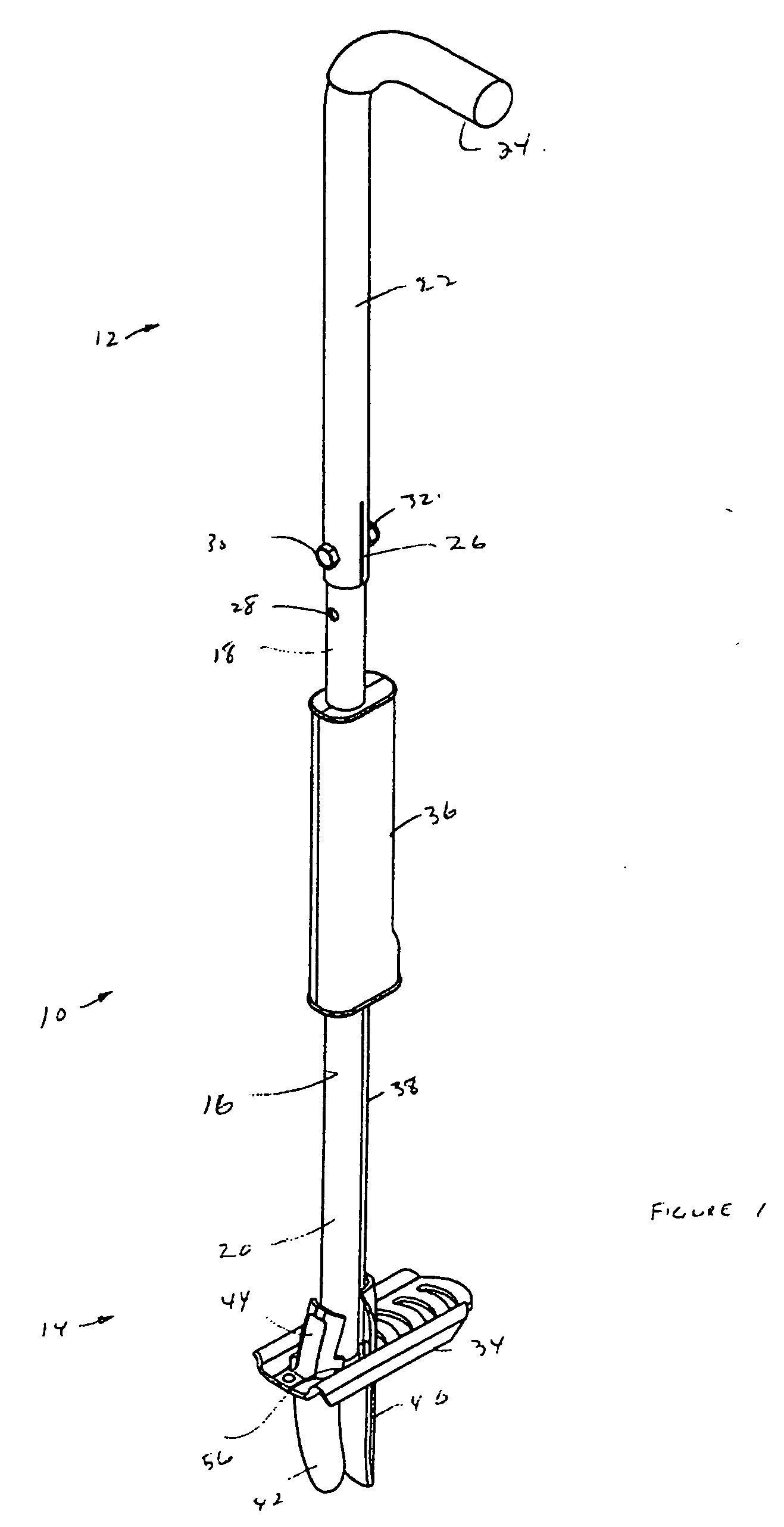
[0015] Referring primarily to FIG. 1, a weed puller 10 is shown with an upper part 12 towards the top of the figure and a lower part 14 towards the bottom of the figure. When oriented as in FIG. 1, the top of the weed puller 10 may be roughly mid thigh to chest high to a person standing next to the weed puller 10, for example with the top of the weed puller 10 at about waist height. While being inserted into the soil or pulling a weed from the soil, the weed puller may be oriented roughly vertically as shown in FIG. 1 or at some angle, for example up to about 45 degrees, from vertical that keeps the upper part 12 above the lower part 14. In the absence of any contrary indication, the words up, upper, top, proximal or other similar words may be used interchangeably to indicate elements, parts of elements, movements of elements or positions of elements closer to the top of the weed puller 10 as shown in FIG. 1 while the words down, lower, bottom, distal or other similar words may be u...


PUM


Abstract

An apparatus for pulling weeds has a body and a reciprocating element able to move upwards or downwards relative to the body. A first blade is attached to or integral with the lower end of the body. A retainer attached to the body holds an intermediate portion of a second blade relative to the body, but allows the second blade to pivot between open and closed positions. When the reciprocating element is in a lower position, the second blade is held in, or allowed to pivot to, its open position. When the reciprocating element is in an upper position, the second blade is held in the closed position by the reciprocating element. The reciprocating element may be biased towards the upper position. The rotating blade, when in the open position, may prevent the reciprocating element from moving to the upper position.

Description

[0001] This is an application claiming the benefit under 35 USC 119(e) to U.S. Provisional Application No. 60 / 679,973 filed May 12, 2005. This application also claims priority to Canadian Application Serial No. CA 2,507,157 filed May 12, 2005. Application Ser. Nos. 60 / 679,973 and CA 2,507,157 are incorporated herein, in their entirety, by this reference to them.FIELD OF THE INVENTION [0002] This invention relates to lawn and garden tools, and more particularly to a manually operated tool for pulling plants such as weeds out of soil. BACKGROUND OF THE INVENTION [0003] The following description of the background of the invention is not an admission that anything discussed below is citable as prior art or part of the knowledge of a person skilled in the art in any country. [0004] Weed pullers, alternately called diggers, weeders, extractors, pickers, removers or other related names, may be used to help a person remove weeds from the ground. A weed puller may be manually operated but pr...

Claims


Application Information

Patent Timeline
Patent Type & Authority Applications(United States)
IPC IPC(8): A01B1/00
CPCA01M21/02A01B1/18
Inventor BASEK, CHARLES
Owner BASEK CHARLES
Why Eureka
Try Eureka