
Electro-mechanical brake

Inactive Publication Date: 2006-12-28
HITACHI LTD
View PDF5 Cites 4 Cited by
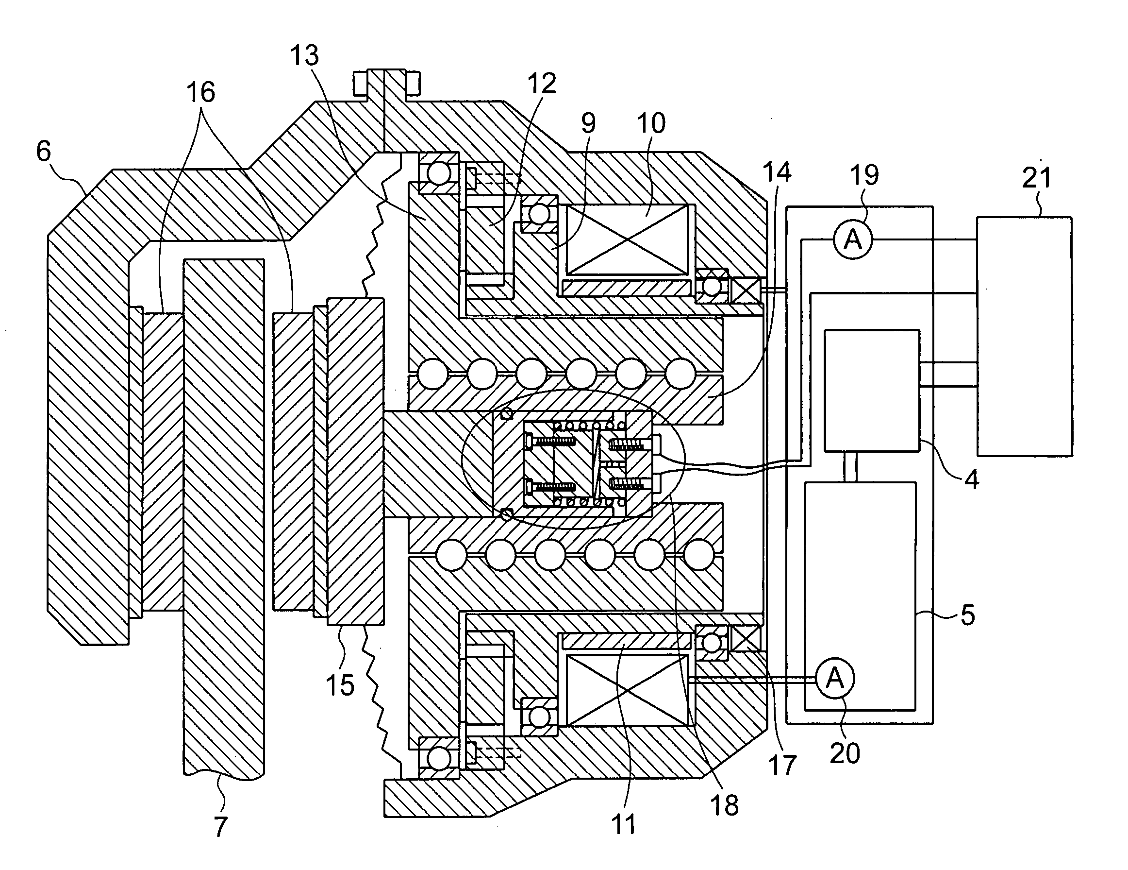
  • Summary
  • Abstract
  • Description
  • Claims
  • Application Information

AI Technical Summary

Benefits of technology

[0004] An object of the present invention is to provide an electro-mechanical brake in which a pad contact position can be correctly detected without a pressing force sensor to enable a braking force to be controlled correctly so that a vehicle can be driven safely.
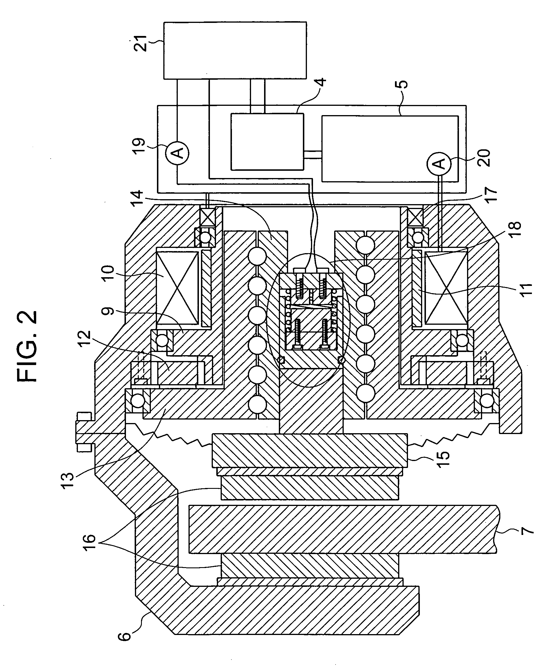
[0005] According to the invention, an electro-mechanical brake capable of detecting a piston position is characterized by a switch arranged at a position where a pad pressing force is borne when the pad pressing force is generated so that the switch is changed between On condition and Off condition in accordance with whether or not the pressing force is less than a certain level, and an elastic member arranged to urge a movable part of the switch in a return direction opposite to a direction of the pressing force to keep the switch at the On condition when the pressing force is less than the certain level and at the Off condition when the pressing force is not less than the certain level. The pad contacting position can be correctly detected by detecting a position of the piston where the switch is changed between On condition and Off condition.
[0006] In the electro-mechanical brake according to the invention, since an electric circuit is not formed to prevent an electric current from flowing therethrough when the pad pressing force is not generated and the electric circuit is formed to allow the electric current to flow therethrough when the pad pressing force is generated so that a pad contact position detector is formed, the pad contact position can be detected accurately during a stoppage or running. According to the invention, since a pressing force sensor for measuring the pad pressing force is unnecessary, a design with taking a reliability of the pressing force sensor under harsh vibration and temperature on vehicle wheel into consideration is not needed, and the electro-mechanical brake of low cost can be provided. Further, by detecting the pad contacting position accurately, an accuracy in controlling the braking force can be improved so that the electro-mechanical brake can provide safe running and braking.

Problems solved by technology

In the above prior art, there is a problem of that since the output value of the pressing force sensor is used to detect the pad contacting position, the accuracy in detecting the pad contacting position is affected by a resolving power of the pressing force sensor for measuring the pressing force, and there is another problem of that since a changing rate of the pad pressing force with respect to a displacement value of the piston is small, it is difficult for an accurate value of the pad pressing force at the timing of contact between the brake pad and the disk rotor to be obtained experimentally.

Method used


Image

  • Electro-mechanical brake
  • Electro-mechanical brake
  • Electro-mechanical brake

Examples


Embodiment Construction

[0015] An embodiment of the invention is explained hereafter in detail with making reference to FIGS. 1-7.

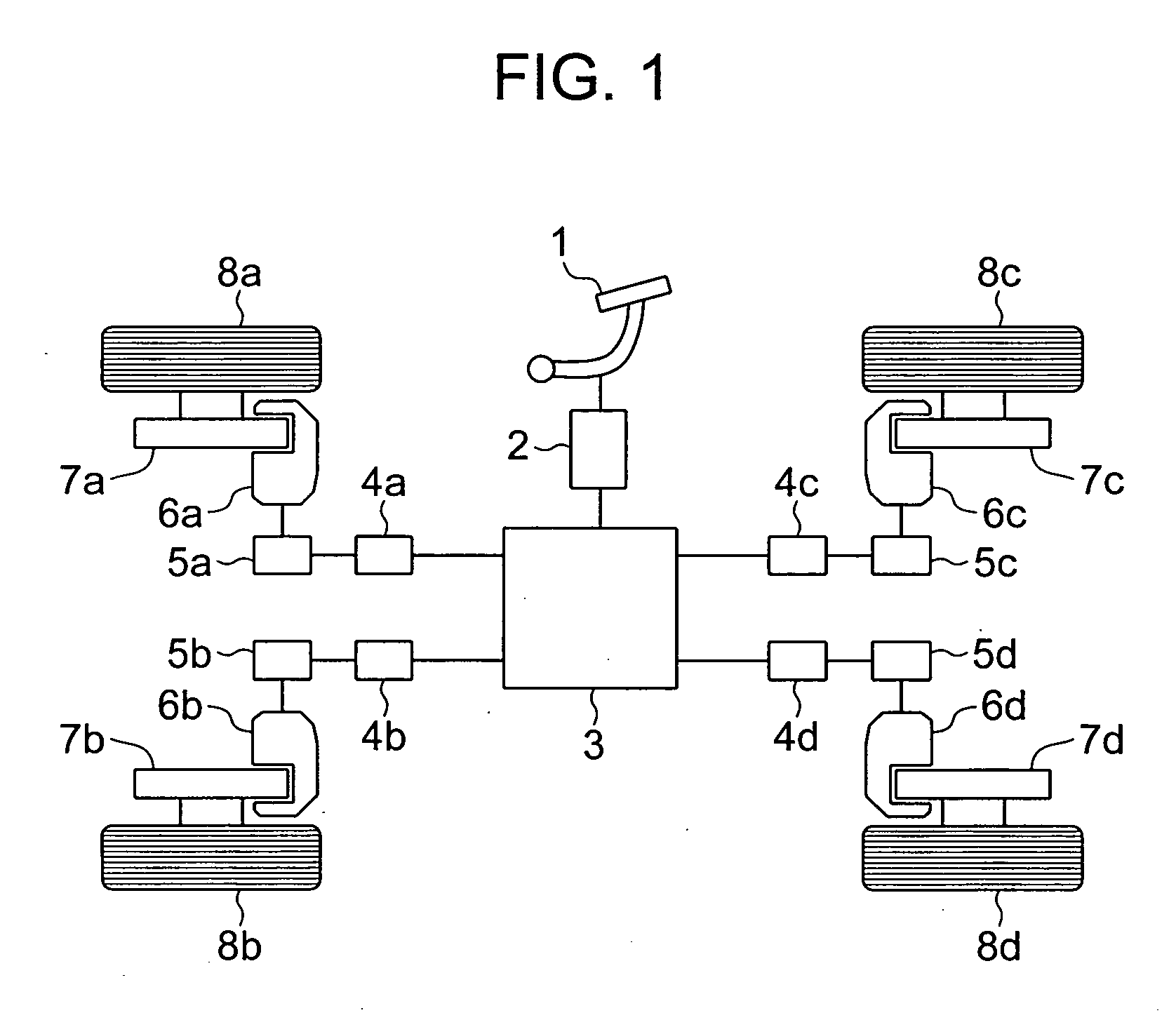
[0016] At first, with making reference to FIG. 1, a system of an electro-mechanical brake system for four-wheels vehicle is schematically explained. In FIG. 1, an electro-mechanical brake of the vehicle has wheels 8a-8d, disk rotors 7a-7d rotatable with the wheels 8a-8d, electro-mechanical brake actuators 6a-6d for pressing the disk rotors 7a-7d, a brake pedal 1, a stroke sensor 2 for converting a moved value of the brake pedal 1 to an electric signal, a main controller 3 for controlling a braking force for each of the wheels in accordance with the electric signal from the stroke sensor 2, electro-mechanical brake controllers 4a-4d for controlling respectively the electro-mechanical brakes for the wheels on the basis of an electric signal output from the main controller 3, and motor drivers 5a-5d for supplying electric currents to motors of the electro-mechanical brake actuator...


PUM


Abstract

An electro-mechanical brake for obtaining a safe traveling and braking with a high accuracy means for detecting a piston position at which a brake pad and a disk rotor contact each other is provided. A pad contact position detecting device in which an electric circuit is not formed to prevent an electric current from flowing therethrough when a pad pressing force is not generated and the electric circuit is formed to enable the electric current to flow therethrough when the pad pressing force is generated is applied to the electro-mechanical brake, whereby a pad contact position can be detected accurately to improve an accuracy in controlling a braking force so that the electro-mechanical brake enabling the safe traveling and braking to be obtained can be provided.

Description

BACKGROUND OF THE INVENTION [0001] The present invention relates to an electro-mechanical brake in which a brake pad is driven by a motor to generate a braking force. [0002] JP-A-2004-92812 discloses an example of an electro-mechanical brake for automobile in which a motor other than a hydraulic means drives a brake pad to generate a braking force. In this example, a disk brake system of floating type in which a disk rotor is clamped between brake pads of a pair by the motor, a ball-screw mechanism for converting a rotation of the motor to a linear movement and a linearly movable part of the ball-screw mechanism. In this electro-mechanical brake, a piston position (pad contact position) at which the brake pads contact the disk rotor is detected, a piston is moved with respect to the pad contact position to adjust a clearance (pad clearance) between the brake pad and the disk rotor and control a pad pressing force. Therefore, in such electro-mechanical brake, an accuracy in determini...

Claims


Application Information

Patent Timeline
IPC IPC(8): B60T8/66F16D65/18
CPCF16D65/18F16D2121/24F16D2066/005F16D2066/003
Inventor KAWAHARA, YOSHINARIYOKOYAMA, ATSUSHISAITO, HIROYUKI
Owner HITACHI LTD
Learn More