Optical fingerprint detecting system

Inactive Publication Date: 2020-10-22
HIMAX TECH LTD
View PDF0 Cites 0 Cited by
  • Summary
  • Abstract
  • Description
  • Claims
  • Application Information

AI Technical Summary

Benefits of technology

The present invention is about an optical fingerprint detecting system that uses differential signaling to prevent interference from noise sources. The aim is to accurately detect fingerprints.

Problems solved by technology

Placing a fingerprint button on the front surface of the mobile devices is unfortunately in contradiction with the trend toward a bigger touchscreen that can accommodate more functions as the mobile devices become more powerful.
However, the optical fingerprint detection may be susceptible to some noise sources.

Method used


Image

  • Optical fingerprint detecting system
  • Optical fingerprint detecting system
  • Optical fingerprint detecting system

Examples


first embodiment

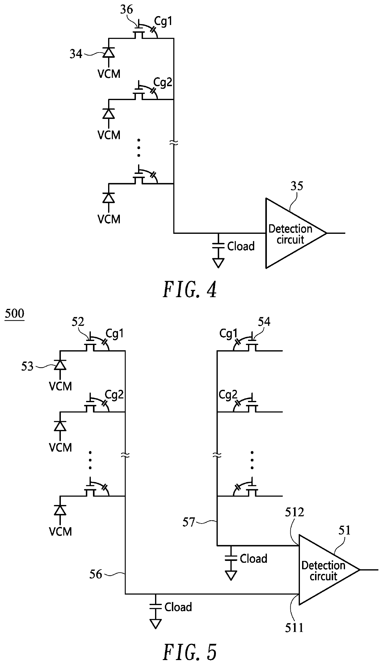
[0023]FIG. 5 shows a circuit diagram illustrating an optical fingerprint detecting system 500 according to the present invention capable of overcoming the drawbacks associated with FIG. 4. Only one channel (or column) of cells has been illustrated for brevity. According to one aspect of the embodiment, differential signaling is adopted in the embodiment. Specifically, the system 500 may include a detection circuit 51 with a differential pair of inputs (e.g., a positive input and a negative input). In one exemplary embodiment, the detection circuit 51 may include a differential amplifier that amplifies difference (voltage) between the two inputs (of the differential pair) but suppresses any voltage common to the two inputs (of the differential pair).

[0024]The optical fingerprint detecting system 500 of the embodiment may include first (sense) switches 52 that are electrically connected at first ends to (first) photo detectors 53 respectively, and are electrically connected at second ...

third embodiment

[0029]FIG. 7 shows a circuit diagram illustrating an optical fingerprint detecting system 700 according to the present invention capable of overcoming the drawbacks associated with FIG. 4. Only one channel (or column) of cells has been illustrated for brevity. Specifically, each channel may include plural first switches 52 and one second switch 54. The first switches 52 and the second switch 54 are electrically connected at first ends to plural first photo detectors 53 and a second photo detector 55 respectively, and are electrically connected at second ends together to a first input 511 of a detection circuit 51 via a sense line 56. According to one aspect of the embodiment, the second switch 54 (e.g., top one) and the second photo detector 55 in a channel are covered by a light shielding cover 61, while others (first) switches 52 and the first photo detectors 53 of the same channel are not covered by the light shielding cover 61 (but in the detection area 22).

[0030]In operation, t...

fourth embodiment

[0031]FIG. 8A and FIG. 8B show circuit diagrams illustrating an optical fingerprint detecting system 800 according to the present invention capable of overcoming the drawbacks associated with FIG. 4. The system 800 is similar to the system 600 (FIG. 6B) with the exception that the second photo detectors 55 of the present embodiment are individually light-blocked (or light-insensitive) while they are manufactured. Therefore, the light shielding cover 61 as used in the system 600 (FIG. 6A) is not required. Specifically, the first photo detectors 53 are electrically connected to the sense line 56 via the first switches 52 respectively, and the second photo detectors 55 are electrically connected to the reference line 57 via the second switches 54 respectively. The system 800 may include cells 31 (e.g., red-green-blue cells or RGB cells), through which light (e.g., generated by a backlight 32 of a liquid crystal display) passes and then illuminates the surface of a finger. The light ref...


PUM


Abstract

An optical fingerprint detecting system includes a detection circuit with a differential pair of two inputs including a first input and a second input; a plurality of first photo detectors; a plurality of first switches that are electrically connected at first ends to the first photo detectors respectively, and are electrically connected at second ends together to the first input of the detection circuit via a sense line; and a plurality of second switches that are electrically connected at first ends together to the second input of the detection circuit via a reference line.

Description

CROSS-REFERENCE TO RELATED APPLICATIONS[0001]This application claims the benefit of U.S. Provisional Application No. 62 / 837,022, filed on Apr. 22, 2019, the entire contents of which is herein expressly incorporated by reference.BACKGROUND OF THE INVENTION1. Field of the Invention[0002]The present invention generally relates to fingerprint detection, and more particularly to an optical fingerprint detecting system with differential signaling.2. Description of Related Art[0003]A mobile device, such as a mobile phone, is a computing device small enough to hold and operate in the hand. The mobile device typically has a touchscreen that occupies substantial front surface (e.g., 70%) of the mobile device.[0004]Fingerprint is one of many forms of biometrics used to identify individuals and verify their identity in order to protect confidential or sensitive data stored in the mobile devices. Fingerprint recognition is not only a secure way of identifying individuals, but also a quick means ...

Claims


Application Information

Patent Timeline
IPC IPC(8): G06K9/00G06K9/03G06K9/20
CPCG06K9/209G06K9/0004H04M1/725G06K9/03G06V40/1318H04M1/0266H04M1/026H04M2250/12G06V40/1329
Inventor HE, JIA-MINGCHANG, YAW-GUANG
Owner HIMAX TECH LTD
Why Eureka
Try Eureka