Joy stick

a stick and stick technology, applied in the field of stick, can solve problems such as quiet decline during operation, and achieve the effect of improving quietness and stable stick operation feeling

Inactive Publication Date: 2006-12-28
MITSUMI ELECTRIC CO LTD
View PDF30 Cites 26 Cited by
  • Summary
  • Abstract
  • Description
  • Claims
  • Application Information

AI Technical Summary

Benefits of technology

[0005] It is therefore an object of the invention to provide a joy stick having a structure in which a stable stick operation feeling is obtained, and an improvement in quietness is attained.
[0012] With this configuration, since the operating stick is returned to the neutral position by the magnetic force between the first member and the second member, even if the operating stick is moved in a diagonal direction with respect to the first and second directions, a stable operation feeling is obtained, and the operational stability improves. In addition, since mechanical noise accompanying the expansion and the contraction of the springs as in the related-art joy stick is not generated when the operating stick is moved, the quietness during the operation improves remarkably.
[0014] With this configuration, a construction of the joy stick becomes simple, and the second member is fixed easily to the lower face of the board and located accurately on the position corresponding to the neutral position of the operating stick.
[0016] With this configuration, since the magnitude of the magnetic force of the second member may be varied freely in a wide range, it is possible to freely impart appropriate relative hardness to the stick operation feeling depending on the application and conditions of use of the joy stick.
[0018] With this configuration, the second member may be mounted easily and speedily, the construction may become simple and a lower cost may be attained.
[0022] With this configuration, since the magnitude of the magnetic force of the first member may be varied in a wide range, it is possible to eliminate the magnetic action by deactivating a power source of the electromagnet when the apparatus is not used. Therefore, even if the casing of the shaft does not have, for example, a hermetic structure, it is possible to reliably prevent the shaft from the attachment of foreign objects such as iron powder to the shaft.

Problems solved by technology

Further, since an expansion and a contraction of the spring in conjunction with the movement of the cranks 3 and 4, mechanical noise peculiar to spring is generated, causing a decline in quietness during the moving operation of the operating stick 5.

Method used


Image

  • Joy stick
  • Joy stick
  • Joy stick

Examples


Embodiment Construction

[0038] Embodiments of the invention will be discussed in detail with reference to the accompanying drawings.

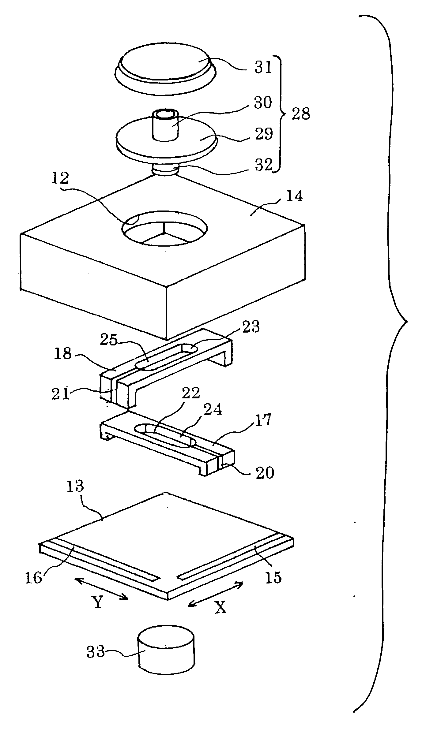
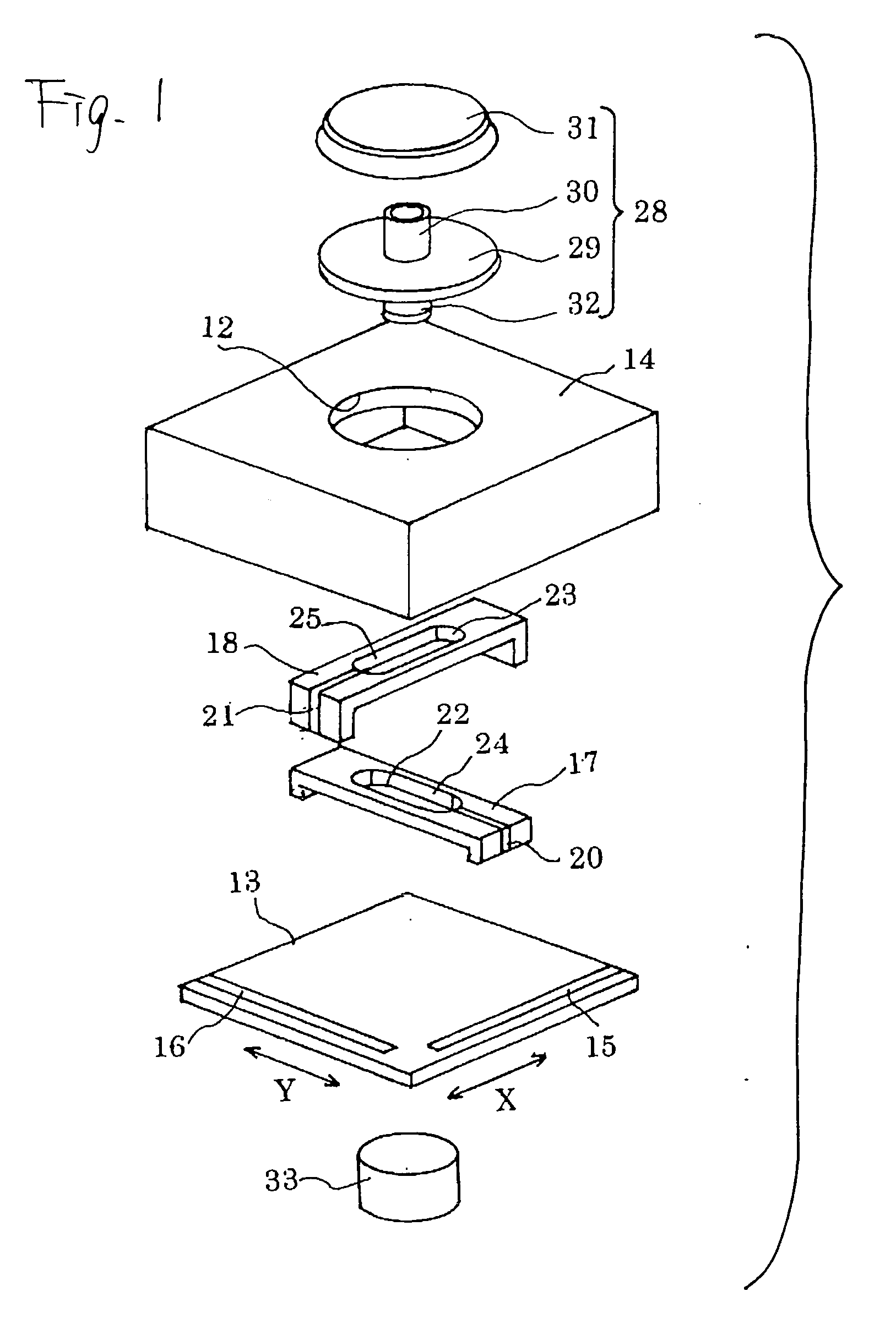
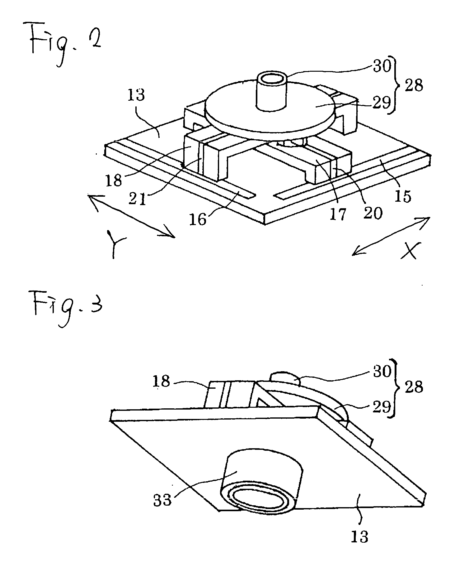
[0039] As shown in FIG. 1, according to a first embodiment of the invention, a box-shaped cover case 14 formed with a central hole 12 is mounted and fixed on a board 13. A lower side of the cover case 14 is open. Further, belt-shaped first contact portions 15 and 16 comprised of copper are respectively provided on adjacent side edges in an upper face of the board 13, and the contact portions 15 and 16 respectively extend in X and Y directions which are perpendicular to each other.

[0040] As shown in FIG. 2, a crank 17 having a U-shaped cross section is disposed on the board 13, and a crank 18 having a U-shaped cross section is mounted on the crank 17. The crank 17 is extended in the Y direction so as to be movable in the X direction. The crank 18 is extended in the X direction so as to be movable in the Y direction. The cranks 17 and 18 are guided in the X direction and the Y...


PUM


Abstract

A board has a first face and a second face opposite to the first face. A movable member is provided on the first face so as to be movable in a first direction. An operating stick is coupled to the movable member, thereby being movable in the first direction from a neutral position thereof. A first magnetic member is provided on the operating stick so as to oppose the first face. A second magnetic member is fixed on the second face so as to oppose the neutral position. The first magnetic member and the second magnetic member are configured to be attractive to each other.

Description

BACKGROUND OF THE INVENTION [0001] The present invention relates to a joy stick. [0002] As shown in FIGS. 10 and 11, a related-art joy stick for use in a game machine or the like comprises a casing 1; a board 2 covered by the casing 1; cranks 3 and a crank 4 disposed on the board 2 so as to be movable in an X direction and a Y direction, respectively; and an operating stick 5 provided on the casing 1. The operating stick 5 comprises a shaft 6, a circular flange 7 provided on an intermediate portion of the shaft 6, and a knob 8 provided on an upper end portion of the shaft 6. A lower end portion of the shaft 6 is engaged in central portions of the cranks 3 and 4. Springs 9 and 10 are respectively interposed between the respective one of the cranks 3 and 4 and the board 2. [0003] According to the above-described configuration, as shown in FIG. 12, by a moving operation of the operating stick 5, the cranks 3 and 4 are moved in an X direction and a Y direction respectively, against forc...

Claims


Application Information

Patent Timeline
Patent Type & Authority Applications(United States)
IPC IPC(8): G09G5/08G06F3/0338
CPCG05G5/05G05G2009/04766G05G2009/04714G05G9/047
Inventor ISHIMARU, HIROSHI
Owner MITSUMI ELECTRIC CO LTD
Why Eureka
Try Eureka