Thermal image forming apparatus

Inactive Publication Date: 2006-12-28
SAMSUNG ELECTRONICS CO LTD
View PDF1 Cites 6 Cited by
  • Summary
  • Abstract
  • Description
  • Claims
  • Application Information

AI Technical Summary

Benefits of technology

[0009] The foregoing and/or other aspects of the present general inventive concept are achieved by providing a thermal image forming apparatus including a platen roller, a thermal head facing a lower circumferential surface of the platen roller to form a first printing location and facing an upper circumferential surface of the platen roller to form

Problems solved by technology

Therefore, it is difficult to align image positions (registration) on the top and bottom surfaces of the recording medium P due to a change of the conveying path from the first conveying path to the seco

Method used


Image

  • Thermal image forming apparatus
  • Thermal image forming apparatus
  • Thermal image forming apparatus

Examples


Example

[0023] The present invention will now be described more fully with reference to the accompanying drawings, in which exemplary embodiments of the invention are shown.

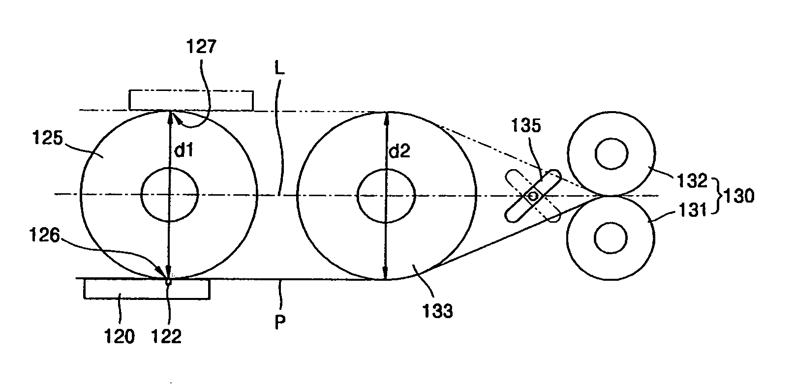
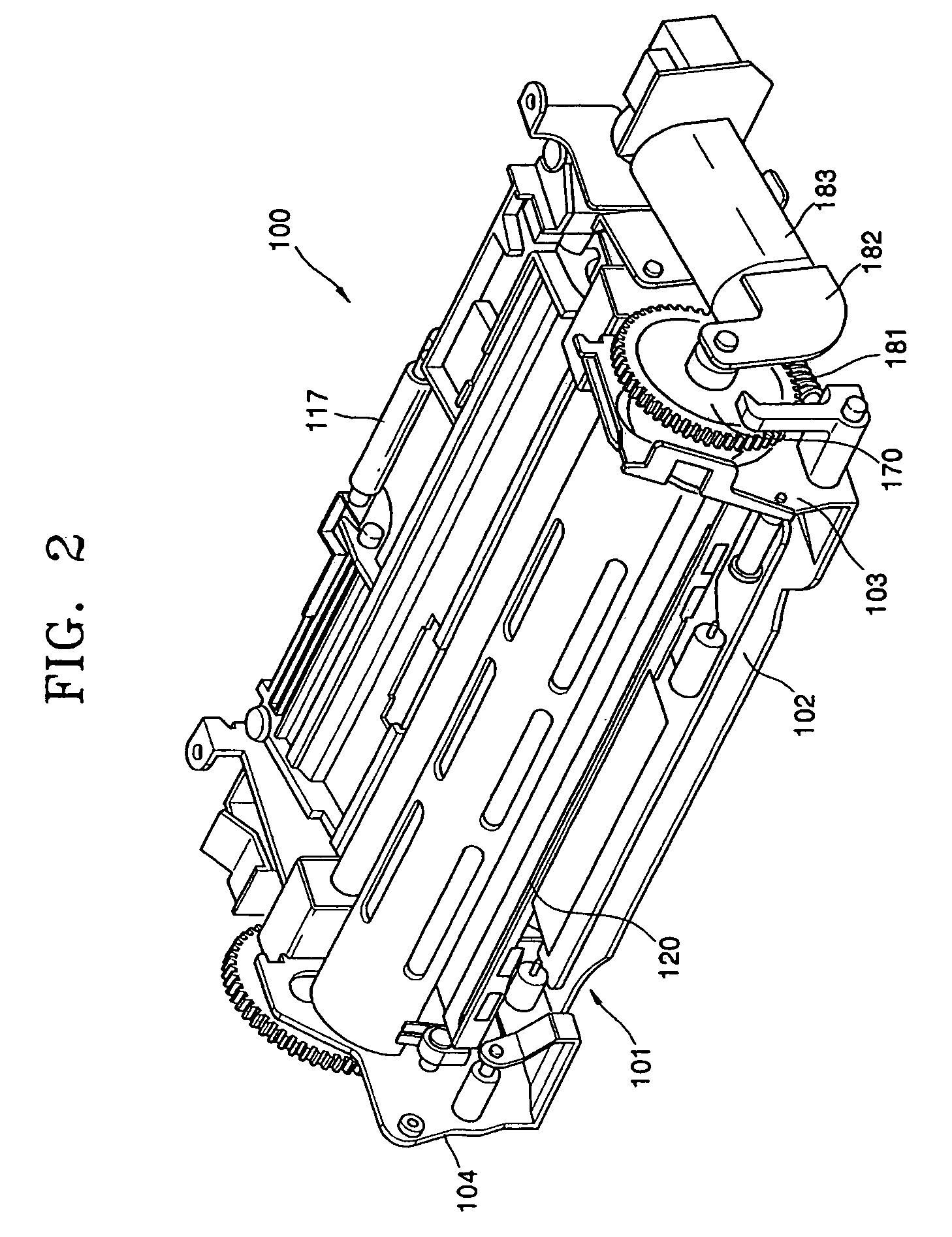
[0024]FIGS. 2 and 3 are a perspective view and a sectional view, respectively, of a thermal image forming apparatus 100 according to an embodiment of the present invention general inventive concept, respectively. FIG. 4 is a sectional view of FIG. 3 illustrating an operation of the thermal image forming apparatus, and FIG. 5 is a sectional view illustrating a recording medium used in the thermal image forming apparatus according to an embodiment of the present invention.

[0025] Referring to FIGS. 2 through 4, the thermal image forming apparatus 100 includes a frame 101. The frame 101 includes a lower base 102, and two side plates 103 and 104 disposed upright on both opposite sides of the lower base 102. A cassette 110 (see FIG. 3) into which a recording medium P is loaded is mounted on one another side of the frame 101....


PUM


Abstract

A thermal image forming apparatus includes a platen roller, a thermal head facing a lower circumferential surface of the platen roller to form a first printing location and facing an upper circumferential surface of the platen roller to form a second printing location, a conveying part to convey a recording medium such that the recording medium passes through the first and second printing locations, and a guide roller to prevent the recording medium from being bent near the first and second printing locations by supporting the recording medium between the platen roller and the conveying part.

Description

CROSS-REFERENCE TO RELATED APPLICATIONS [0001] This application claims the benefit under 35 U.S.C. §119 of Korean Patent Application No. 2005-56076, filed on Jun. 28, 2005, in the Korean Intellectual Property Office, the disclosure of which is incorporated herein in its entirety by reference. BACKGROUND OF THE INVENTION [0002] 1. Field of the Invention [0003] The present general inventive concept relates to a thermal image forming apparatus, and more particularly, to a thermal image forming apparatus capable of forming images on both sides of a recording medium. [0004] 2. Description of the Related Art [0005]FIG. 1 is a schematic sectional view of a conventional thermal image forming apparatus that can print images on both sides of a recording medium. Referring to FIG. 1, the conventional thermal image forming apparatus 10 includes a thermal head 11 facing a recording medium P to apply heat thereto, a platen roller 15 pressing the recording medium P toward the thermal head 11, and a...

Claims


Application Information

Patent Timeline
IPC IPC(8): G01D15/10
CPCB41J13/0045B41J3/60
Inventor HAN, DONG-HUN
Owner SAMSUNG ELECTRONICS CO LTD
Why Eureka
Try Eureka