Process cartridge and image forming apparatus

a technology of image forming apparatus and process cartridge, which is applied in the direction of electrographic process apparatus, instruments, optics, etc., can solve the problems of forming image and prone to damage of the force receiving portion

Active Publication Date: 2007-07-12
CANON KK
View PDF18 Cites 231 Cited by
  • Summary
  • Abstract
  • Description
  • Claims
  • Application Information

AI Technical Summary

Benefits of technology

[0009] It is another object of the present invention to provide a process cartridge in which the electrophotographic photosensitive drum and the developing roller are contactable to each other and spaceable from each other with which when the process cartridge is handled, or when the process cartridge is transported, the force receiving portion is not damaged.

Problems solved by technology

If this occurs, non-uniformity may result in the formed image.
Therefore, when the user handles the process cartridge, and / or when the process cartridge is transported, the force receiving portion tends to be damaged.

Method used


Image

  • Process cartridge and image forming apparatus
  • Process cartridge and image forming apparatus
  • Process cartridge and image forming apparatus

Examples


first embodiment

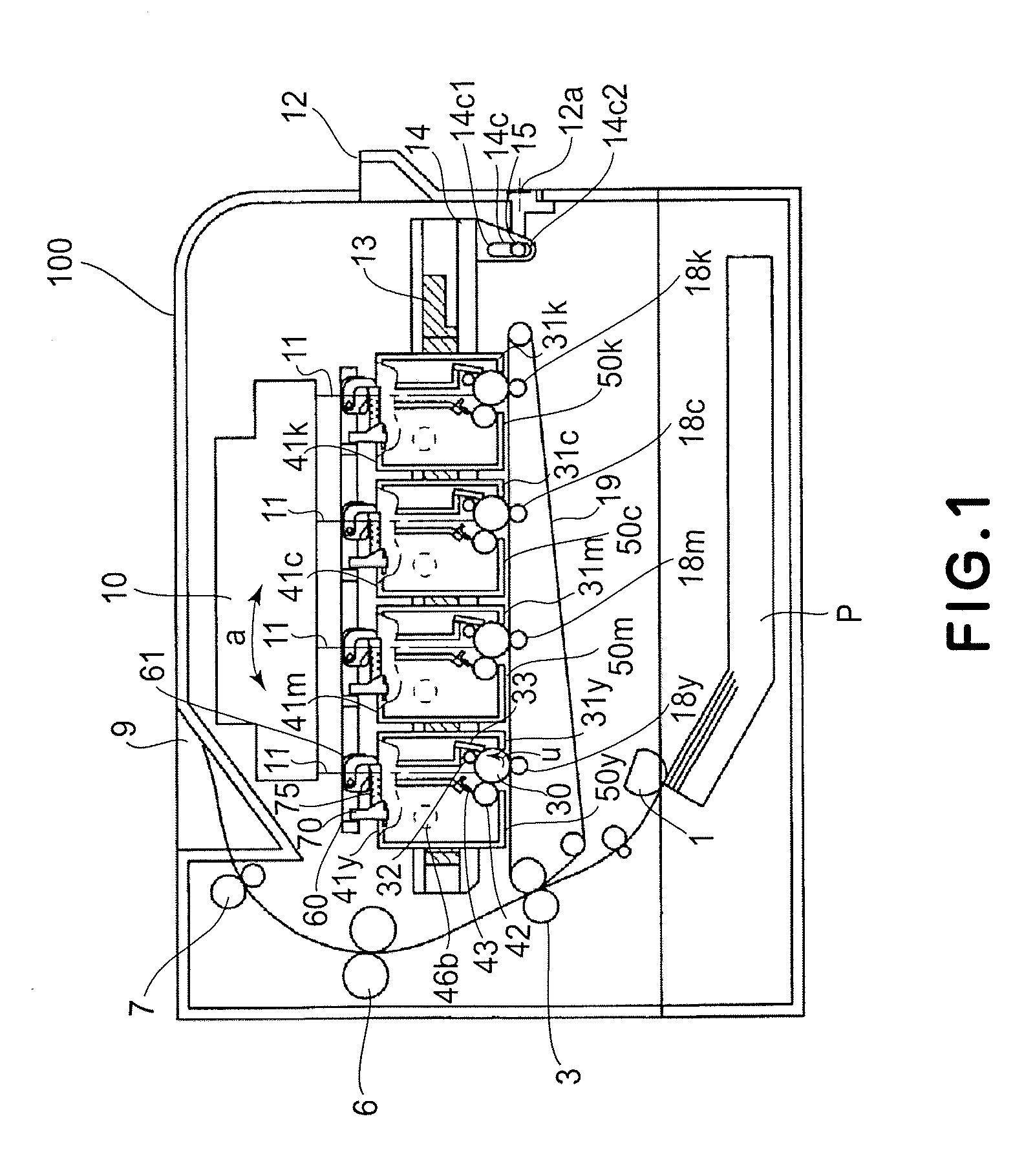
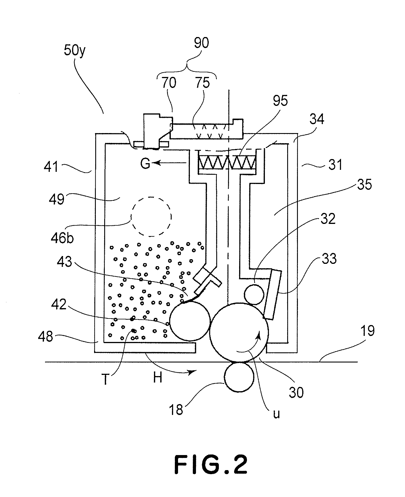
[0081] Referring to FIGS. 1-4, the process cartridge and the electrophotographic image forming apparatus according to the first embodiment of the present invention.

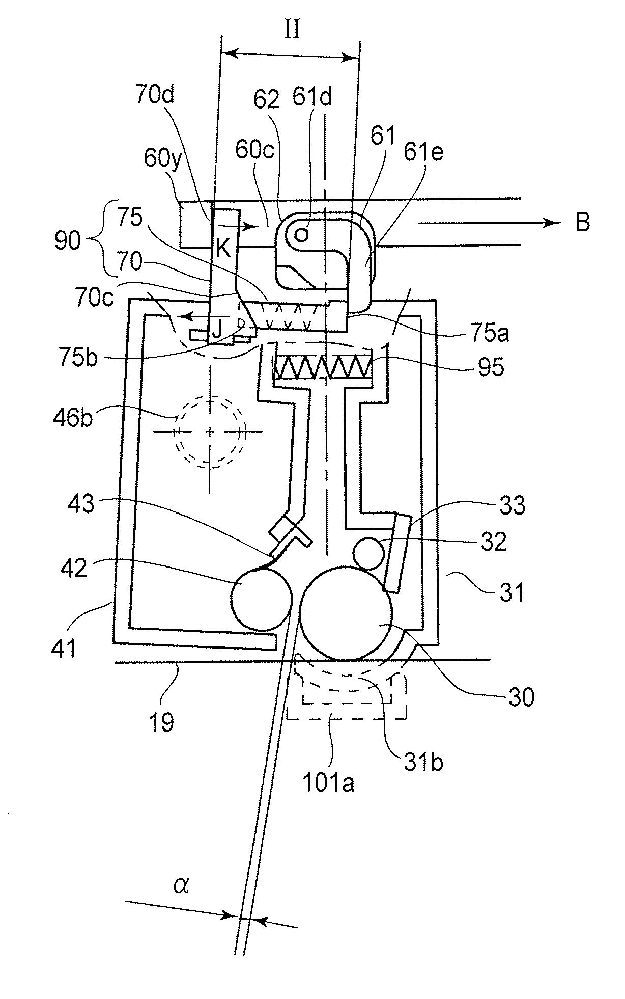
[0082]FIG. 1 shows an electrophotographic image forming apparatus (main assembly of the apparatus) 100 including process cartridges (cartridges) 50y, 50m, 50c, 50k detachably mounted. The cartridges 50y, 50m, 50c, 50k contain or accommodate yellow color toner (developer), magenta color toner (developer), cyan color toner (developer) and black color toner (developer), respectively. FIG. 2 is a sectional side elevation of the cartridge alone; FIGS. 3 and 4 are illustrations of removing the cartridges 50y, 50m, 50c, 50k from the main assembly 100 of the apparatus.

[General Arrangement of Electrophotographic Image Forming Apparatus]

[0083] As shown in FIG. 1, the main assembly 100 of the apparatus, the electrophotographic photosensitive drums (photosensitive drums) 30y, 30m, 30c, 30k are exposed to the laser beams 11 modulat...

second embodiment

[0144] In the first embodiment, the cartridges 50y, 50m, 50c, 50k are mounted to the main assembly 100 of the apparatus in the direction substantially perpendicular to the axis of the photosensitive drum 30. In Embodiment 2, the cartridges 450y, 450m, 450c, 450k are mounted to the main assembly 401 of the electrophotographic image apparatus (main assembly of the apparatus) in the direction substantially parallel with the axial direction of the electrophotographic photosensitive drum the photosensitive drum) 430. In the following description, the points different from the first embodiment will be described mainly.

[General Arrangement of Electrophotographic Image Forming Apparatus]

[0145] As shown in FIG. 39FIGS. 41, the main assembly 401 of the apparatus is loaded with the cartridges 450y, 450m, 450c, 450k in the direction (arrow K) substantially parallel with the axial direction (longitudinal direction) of the photosensitive drum 430. In this embodiment, the cartridges 450y, 450m, ...

third embodiment

[0160] This embodiment relates to a modification of the force receiving device.

[0161] This embodiment will be described also with a yellow cartridge 250y accommodating a yellow color developer as an exemplary cartridge.

[0162] As shown in FIG. 51-FIG. 54, the developing unit 241 is provided with a force receiving member 277 (force receiving device).

[0163] The force receiving member 277 includes a shaft portion 277c supported rotatably on the developing device frame 248, a first force receiving portion 277a on which the first force application member 261 is actable, and a second force receiving portion 277b on which the second force application member 263 is actable. The force receiving member 277 is integrally constituted by the first force receiving portion and the second force receiving portion. The spring 298 has one end fixed to the force receiving member 277 and another end fixed to the developing device frame 248. The force receiving member 277 is kept in the state shown in ...


PUM


Abstract

A process cartridge detachably mountable to a main assembly of an electrophotographic image forming apparatus, the main assembly including an opening, a door movable between a close position for closing the opening and an open position for opening the opening, a first force application member movable with movement of the door from the open position to the closing position and a second force application member movable by a driving force from a driving source, the process cartridge includes an electrophotographic photosensitive drum; a developing roller for developing an electrostatic latent image formed on the electrophotographic photosensitive drum; a drum unit containing the electrophotographic photosensitive drum; a developing unit which contains the developing roller and which is movable relative to the drum unit such that developing roller is movable between a contact position in which the developing roller is contacted to the electrophotographic photosensitive drum and a spaced position in which the developing roller is spaced from the electrophotographic photosensitive drum; and a force receiving device including a first force receiving portion for receiving a force from the first force application member by movement of the door from the open position to the close position in the state that process cartridge is mounted to the main assembly of the apparatus through the opening, and a second force receiving portion movable from a stand-by position by movement of the first force receiving portion by a force received from the first force application member, wherein the second force receiving portion takes a projected position for receiving a force from the second force application member to move the developing unit from the contact position to the spaced position, the projected position being higher than the stand-by position.

Description

FIELD OF THE INVENTION [0001] The present invention relates to a process cartridge in which an electrophotographic photosensitive drum and a developing roller actable on the electrophotographic photosensitive drum which are contactable to each other and spaceable from each other, and an electrophotographic image forming apparatus to which said process cartridge is detachably mountable. RELATED ART [0002] In an image forming apparatus using an electrophotographic image forming process, a process cartridge type is conventional wherein an electrophotographic photosensitive drum and a developing roller actable on the electrophotographic photosensitive drum are unified into a process cartridge detachably mountable to a main assembly of the image forming apparatus. With the process cartridge type, the maintenance operation of the apparatus can be carried out in effect without the service person. Therefore, the process cartridge type is widely used in the field of electrophotographic image...

Claims


Application Information

Patent Timeline
Patent Type & Authority Applications(United States)
IPC IPC(8): G03G21/18
CPCG03G21/1825G03G2215/0119G03G2221/169G03G21/1842G03G2221/1869G03G21/1839G03G21/1623G03G2221/1861G03G21/18G03G15/02G03G15/00G03G21/1803G03G21/1647G03G21/1676G03G21/1814
Inventor YOSHIMURA, AKIRAMURAYAMA, KAZUNARINITTANI, SUSUMUNUMAGAMI, ATSUSHI
Owner CANON KK
Why Eureka
Try Eureka