Novel reflector based optical design

Inactive Publication Date: 2006-12-28
CARMANAH TECHNOLOGIES INC
View PDF19 Cites 58 Cited by
  • Summary
  • Abstract
  • Description
  • Claims
  • Application Information

AI Technical Summary

Benefits of technology

[0007] The LEDs and the reflector may all be mounted on a planar circuit board. A beacon design utilizing a planar circuit board is desirable due to its suitability for automated production. This design eliminates the requirement for a diffusion filter to smooth out the ripples in many applications, as ripples are reduced to an acceptable level.
[0008] In one aspect of

Problems solved by technology

Adding a diffusion filter that spreads the light horizontally to smooth out the beam profile can eliminate these ripples, but may attenuate the light intensity.
There are at least two difficulties in utilizing these new LEDs for beacons.
The newer LEDs have wide (lambertian) beam patterns which makes col

Method used


Image

  • Novel reflector based optical design
  • Novel reflector based optical design
  • Novel reflector based optical design

Examples


Embodiment Construction

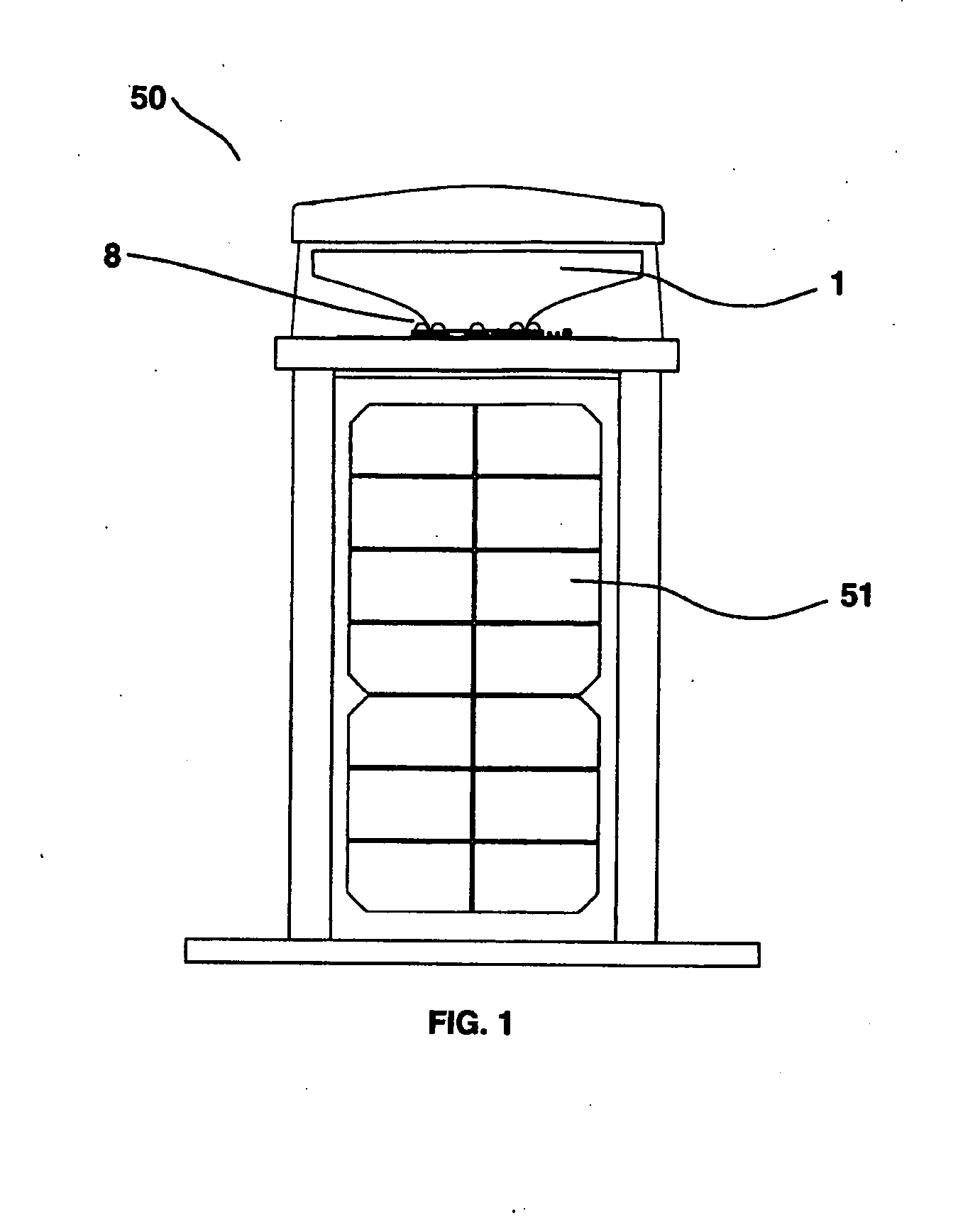
[0026]FIG. 1 depicts a beacon 50 according to an embodiment of the invention including a reflector 1, wide-angle LEDs 8 and one or more solar panels 51. The beacon 50 may be utilized in applications that require a narrow beam of light such as marine or aviation navigation.

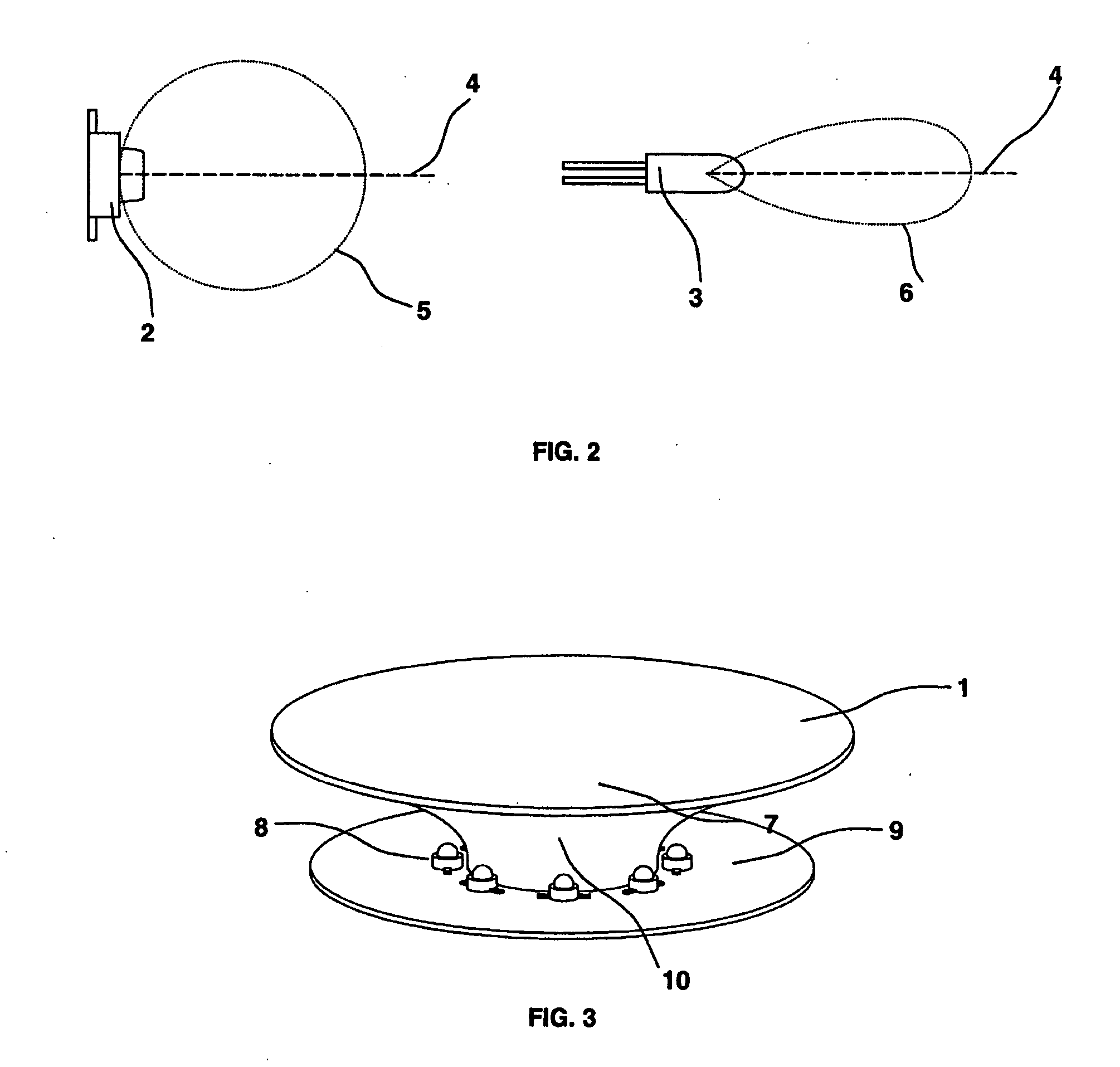
[0027]FIG. 2a depicts a beam pattern 5 of the typical wide-angle LED 8 including the axis of maximum intensity 4. FIG. 2b depicts a narrow beam pattern 6 of the typical 5 mm LED 3.

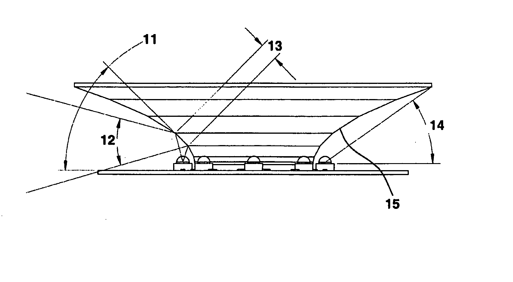
[0028] Referring to FIGS. 3, 4 and 5, there is shown a reflector arrangement according to the invention. A plurality of wide-angle (Lambertian) LEDs (8) are arranged in a circular array, pointing up at a curved or substantially conical reflector (1) concentric with the ring of LEDs 8. Both the LEDs and the reflector are mounted to a planar circuit board 9. The reflector is designed to reflect rays directed upward above some maximum angle 14 shown in FIG. 4, and rays inward 17 (see FIG. 5) toward the middle of the ring so that they go ou...


PUM


Abstract

A novel optical design based on a faceted conical or curved reflector centered within an upward facing circular array of light emitting diodes (LED) and protected by a transparent cover.

Description

RELATED APPLICATIONS [0001] This application claims priority from U.S. Provisional Patent Application Ser. No. 60 / 595,316 filed Jun. 22, 2005 which is hereby incorporated by reference.FIELD OF THE INVENTION [0002] This invention relates to novel optical design based on a conical reflector (1) centered within an upward facing circular array of LEDs (8). BACKGROUND OF THE INVENTION [0003] Navigational light beacons typically emit a fan beam that is vertically narrow and broad in the horizontal plane. Lights of this type must have uniform output around the horizontal plane. [0004] Since the advent of high brightness light emitting diodes (LED), a plethora of beacons have been designed to take advantage of the LED. The majority of these beacons utilize a plurality of narrow beam 5 mm LEDs in a circular array, where the axis of maximum intensity is directed outward and lies in the horizontal plane. The light output from the LEDs is typically collimated by an additional refractive optical...

Claims


Application Information

Patent Timeline
IPC IPC(8): F21V7/00
CPCF21V7/0008F21W2111/06F21Y2101/02F21W2111/04F21Y2115/10
Inventor BOOTH, IANJOHNSTON, BROCK
Owner CARMANAH TECHNOLOGIES INC
Why Eureka
Try Eureka