Automated traffic cone handling machine

a technology of automatic handling and traffic cones, applied in traffic signals, applications, roads, etc., can solve the problems of unanticipated force on the part of the driver of the vehicle distributing the cones or collecting them, the flexibility of the handling process is very difficult, and the workers are seriously injured, including fatal injuries,

Inactive Publication Date: 2006-12-28
LIDSTER SCOTT
View PDF10 Cites 25 Cited by
  • Summary
  • Abstract
  • Description
  • Claims
  • Application Information

AI Technical Summary

Benefits of technology

[0014] Accordingly, it is an object of the present invention to provide a new and improved apparatus for

Problems solved by technology

However, such cones when exposed to roadway temperatures over 100 degrees F., become very flexible and difficult to handle due to the increased flexibility without compromising the ability to maintain their configuration when set on a roadway.
Some workers have suffered serious injuries, including fatal injuries.
Moreover a truck or vehicle used to distribute or collect the cones, may undergo unexpected movements, such as change in direction, braking or acceleration which further subjects the personnel on vehicles distributing the cones, or collecting them, to unanticipated forces.
In addition changes in weather, such as a thunder storm, can add slippery conditions creating an increased risk of accidents when manually handling such cones.
Some prior art system developed for this purpose, which have numerous problems, are the automated systems proposed in U.S. Pat. N

Method used


Image

  • Automated traffic cone handling machine
  • Automated traffic cone handling machine
  • Automated traffic cone handling machine

Examples


Embodiment Construction

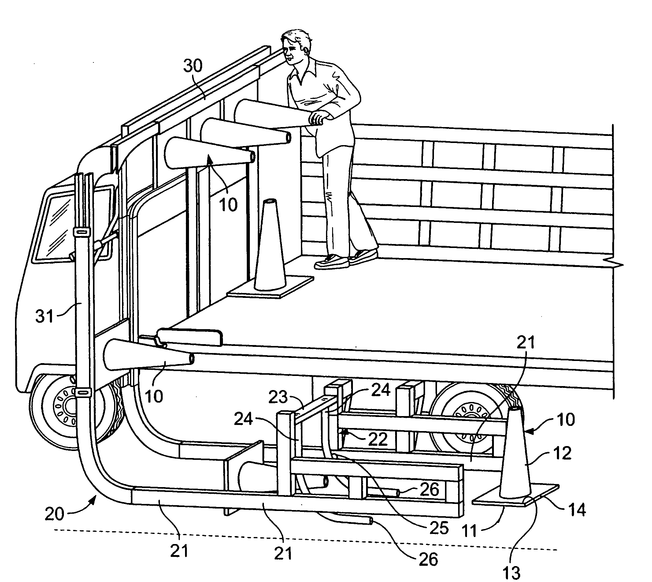
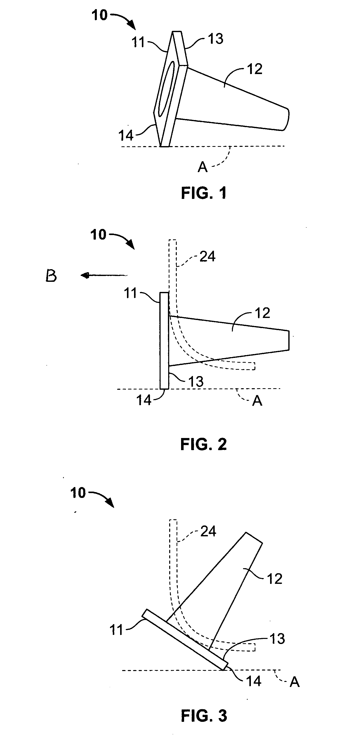
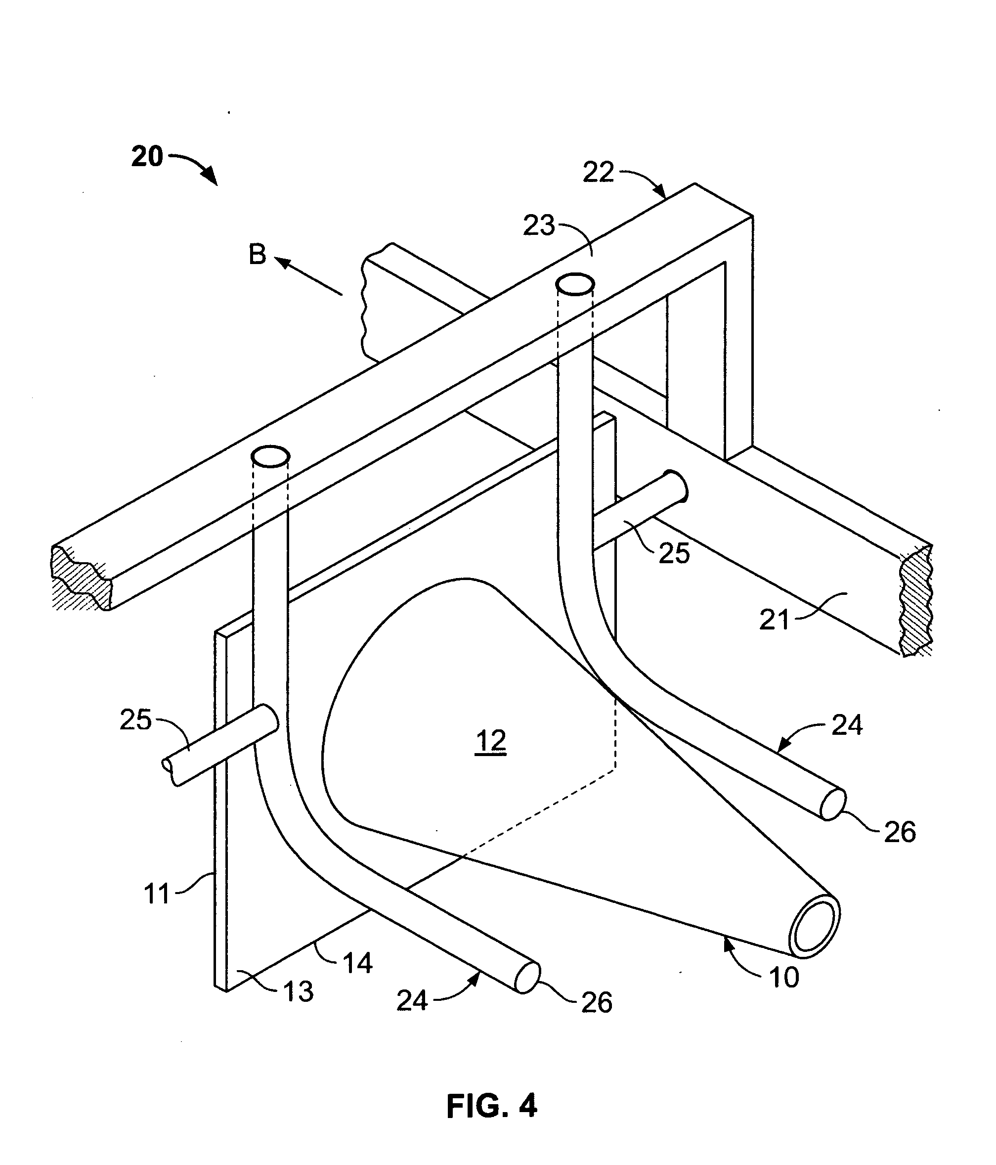
[0044] At the heart of the invention is a simple but elegant concept for handling traffic cones on roadway surfaces. This novel concept can be appreciated by reference to FIGS. 1, 2 and 3 where a traffic cone 10, illustrated lying on the roadway A in a horizontal position between the spaced apart rails (rails not shown in FIGS. 1 through 3), is brought to an upright position as the rails move in the direction of arrow B (see FIG. 2).

[0045] As can be seen in these figures, each traffic cone has a rectangular base 11 with an integral conical section 12 extending therefrom to the top to complete the cone, which is a common design for such cones. This hollow conical section does not cover the entire top 13 of the rectangular base, allowing the top of the base which is engaged for manipulating the traffic cones according to this invention.

[0046] In operation as the rails move in the direction of arrow B the conical section passes between spaced apart arcuate guides 24 (illustrated in p...


PUM


Abstract

Through the use of a rail system having spaced apart rails tracking above and along a roadway with arcuate guides associated with each rail and a cone magazine sequentially delivering traffic cones in a horizontal position between the rails in front of the arcuate guides, each horizontally disposed cone will be brought to an upright position when the top of its base contacts the guides as a result of friction with the roadway of one edge of the base of the traffic cone and movement of the guides with the rails. In one embodiment the magazine includes a mechanical arm with a cone clamp at its distal end, arranged to move the cone clamp from a cone storage to a location between the rails to sequentially deliver cones to the rail system. An auxiliary system is provided to reposition upright traffic cone from the rail system in a taper for closing off access to roadways. The arcuate guides can be removed, after which the rail system can be used to collect traffic cones by sequentially knocking them down between the rails and employing the arm with the cone clamp to sequentially transport such cones from a location between the rails to a cone storage in the magazine.

Description

FIELD OF THE INVENTION [0001] The present invention relates to an automated system for the deposition and collection of traffic cones on roadway surfaces, and more particularly to an improved traffic cone setting device for automatically depositing traffic cones on roadway surfaces and an automatic device for collecting the same. BACKGROUND OF THE INVENTION [0002] Traffic cones are used on roadways to visually alert motorists to the presence of construction, to delineate or separate moving lanes of traffic from roadside work zones, to close off particular street regions to traffic, or the like. Typically such cones are used as temporary traffic control devices and placed by crews on the roadway to provide guidance to motorists. [0003] The cones themselves are generally of a common design having a rectangular base and a centrally positioned tapering cone extending from the base to the top. These cones are made of an elastomer composition which is flexible but has sufficient rigidity ...

Claims


Application Information

Patent Timeline
IPC IPC(8): E01C5/00
CPCE01F9/014E01F9/70
Inventor LIDSTER, SCOTT
Owner LIDSTER SCOTT
Why Eureka
Try Eureka