Dynamic stabilization system for the spine

a stabilization system and dynamic technology, applied in the field of spinal implants and stabilization systems, can solve problems such as limitations of spinal fusion, and achieve the effect of preventing relative rotation and ensuring the placement of one vertebra

Active Publication Date: 2006-12-28
SPINEWAVE
View PDF32 Cites 396 Cited by
  • Summary
  • Abstract
  • Description
  • Claims
  • Application Information

AI Technical Summary

Benefits of technology

[0015] In one aspect, the dynamic stabilization system may be implanted while the spine of the patient is in flexion, thereby widening the space between the posterior aspects of the adjacent vertebrae. With the spine in flexion, the stabilization system may be readily implanted into one vertebra so that when the flexion is removed the adjacent vertebra will contact the deflectable element. In this way, the deflectable element may provide a certain amount of posterior distraction of the adjacent vertebrae. In some embodiments, the deflectable element is configured with an angled surface that can bear against the adjacent vertebra as the deflectable element is mounted on the bone engaging fastener. With these embodiments, the implantation of the deflectable element itself will distract the adjacent vertebrae and the element will maintain this distraction when the construct is complete.
[0016] The bone engaging fastener may include a shank having bone engaging threads, a threaded stem and a nut configured for engaging the threaded stem. In this embodiment, the deflectable element defines an opening to receive the threaded stem therethrough. The nut then bears on the deflectable element to mount the deflectable element on the fastener. Where the deflectable element is resiliently deformable, the nut is used to compress the element so that the element deforms at the opening to firmly engage the stem of the bone engaging fastener to resist or prevent relative movement between the fastener and the deflectable element. In other embodiments, the threaded stem and the opening in the deflectable element are keyed to prevent relative rotation.

Problems solved by technology

However, spinal fusion has been recognized to have limitations in the treatment of disc degeneration, especially in the earlier stages of the degeneration where it may be unnecessary to eliminate motion of the spinal motion segments.

Method used


Image

  • Dynamic stabilization system for the spine
  • Dynamic stabilization system for the spine
  • Dynamic stabilization system for the spine

Examples


Embodiment Construction

[0078] For the purposes of promoting an understanding of the principles of the invention, reference will now be made to the embodiments illustrated in the drawings and described in the following written specification. It is understood that no limitation to the scope of the invention is thereby intended. It is further understood that the present invention includes any alterations and modifications to the illustrated embodiments and includes further applications of the principles of the invention as would normally occur to one skilled in the art to which this invention pertains.

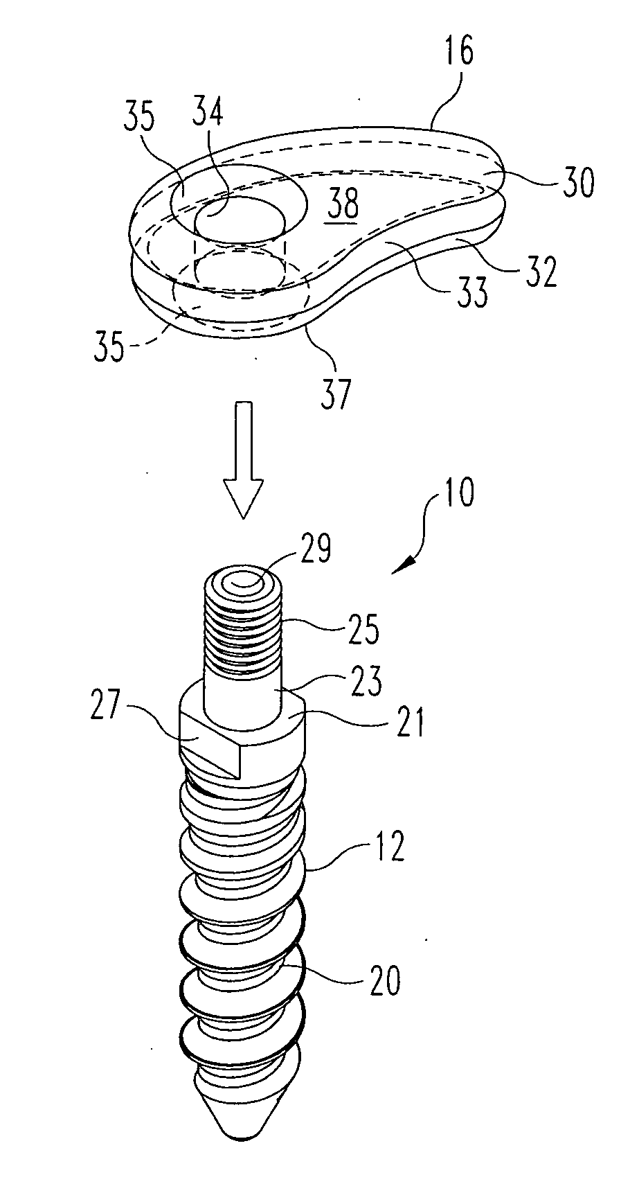
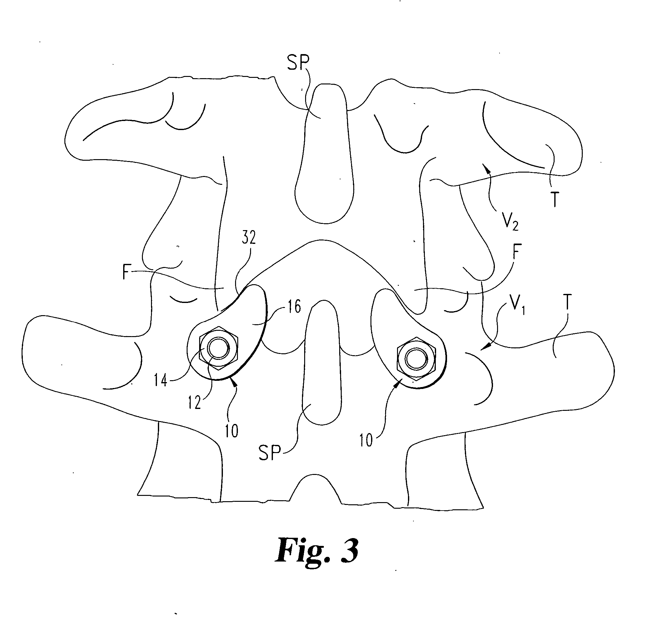
[0079] Referring to FIGS. 3-6, a dynamic stabilization system 10 according to one embodiment of the invention is illustrated. As shown in FIG. 3, the system 10 includes a component engaged within one vertebra V1 and a component that bears against a portion of an adjacent vertebra V2. In particular, the system 10 includes a bone engaging fastener 12 that is configured to engage the body of the vertebra V1 and a...


PUM


Abstract

A system for dynamic stabilization of the spine includes a bone engaging fastener configured to be anchored in a vertebra and a deflectable element mounted on the fastener. The deflectable element or bumper is configured and arranged to contact a portion of an adjacent vertebra, such as the facet, during extension of the spine, while offering no resistance during flexion. In certain embodiments, a cable may be fastened to the bone engaging fastener and arranged to contact a portion of the adjacent vertebra, such as the spinous process, during flexion of the spine. In one surgical technique of the invention, a contralateral approach is used to introduce the bone engaging fastener through the deflectable element and into the vertebra.

Description

REFERENCE TO RELATE APPLICATION [0001] The present application claims priority to co-pending provisional application No. 60 / 673,646, filed on Apr. 21, 2005 and entitled “Interspinous Dynamic Stabilization System”, the entire disclosure of which is incorporated herein by reference.BACKGROUND OF THE INVENTION [0002] The present invention relates to spinal implants and stabilization systems. More particularly, the invention concerns a dynamic stabilization system that is disposed in between adjacent vertebrae. [0003] In the past, the principal protocol for the treatment of the spine has been rigid fixation combined with fusion of the affected vertebral body or intervertebral disc. Arthrodesis, as this approach is known, has been achieved with a variety of rigid fixation elements, such as spinal rods or plates that are rigidly fixed to a vertebra using bone screws, bone bolts and spinal hooks. However, spinal fusion has been recognized to have limitations in the treatment of disc degene...

Claims


Application Information

Patent Timeline
Patent Type & Authority Applications(United States)
IPC IPC(8): A61F2/30
CPCA61B17/7055A61B17/7064A61B2017/90A61B17/842A61B17/8875A61B17/7067A61B17/90
Inventor WALKENHORST, JARED W.LANDRY, MICHAEL E.WILSON, THOMAS G.PAFFORD, JOHN A.KITCHEL, SCOTT H.CARTER, ANDREWCOMEY, CHRISTOPHER
Owner SPINEWAVE
Why Eureka
Try Eureka