Prosthetic implant, and a method and tool for the insertion of same

a technology for prosthetic implants and screws, applied in the field of prosthetic implants, can solve the problems of loose screws, difficult to insert prosthetic implants from the posterior side, and long procedures, and achieve the effect of preventing migration

Inactive Publication Date: 2006-12-28
SPINEWORKS
View PDF11 Cites 82 Cited by
  • Summary
  • Abstract
  • Description
  • Claims
  • Application Information

AI Technical Summary

Benefits of technology

[0007] Also disclosed herein is a prosthetic implant, method, and tool for placing the implant, wherein the implant is angled to provide to correct spinal curvature after placement and wherein the anterior end and the opposite posterior end are rounded to provide ease of placement into the proper location between the vertebrae. The prosthetic implant has serrated edges on the top sides and the bottom sides to allow for purchase or digging into the bone and to prevent migration out of the placed location. Further, th

Problems solved by technology

To insert a prosthetic implant from the posterior side is challenging since the invertebral space in the spinal column is smaller in the posterior side of the spinal column versus the anterior side.
These procedures take much time and do have risks associated with them.
For example, distracting on the scre

Method used


Image

  • Prosthetic implant, and a method and tool for the insertion of same
  • Prosthetic implant, and a method and tool for the insertion of same
  • Prosthetic implant, and a method and tool for the insertion of same

Examples


Embodiment Construction

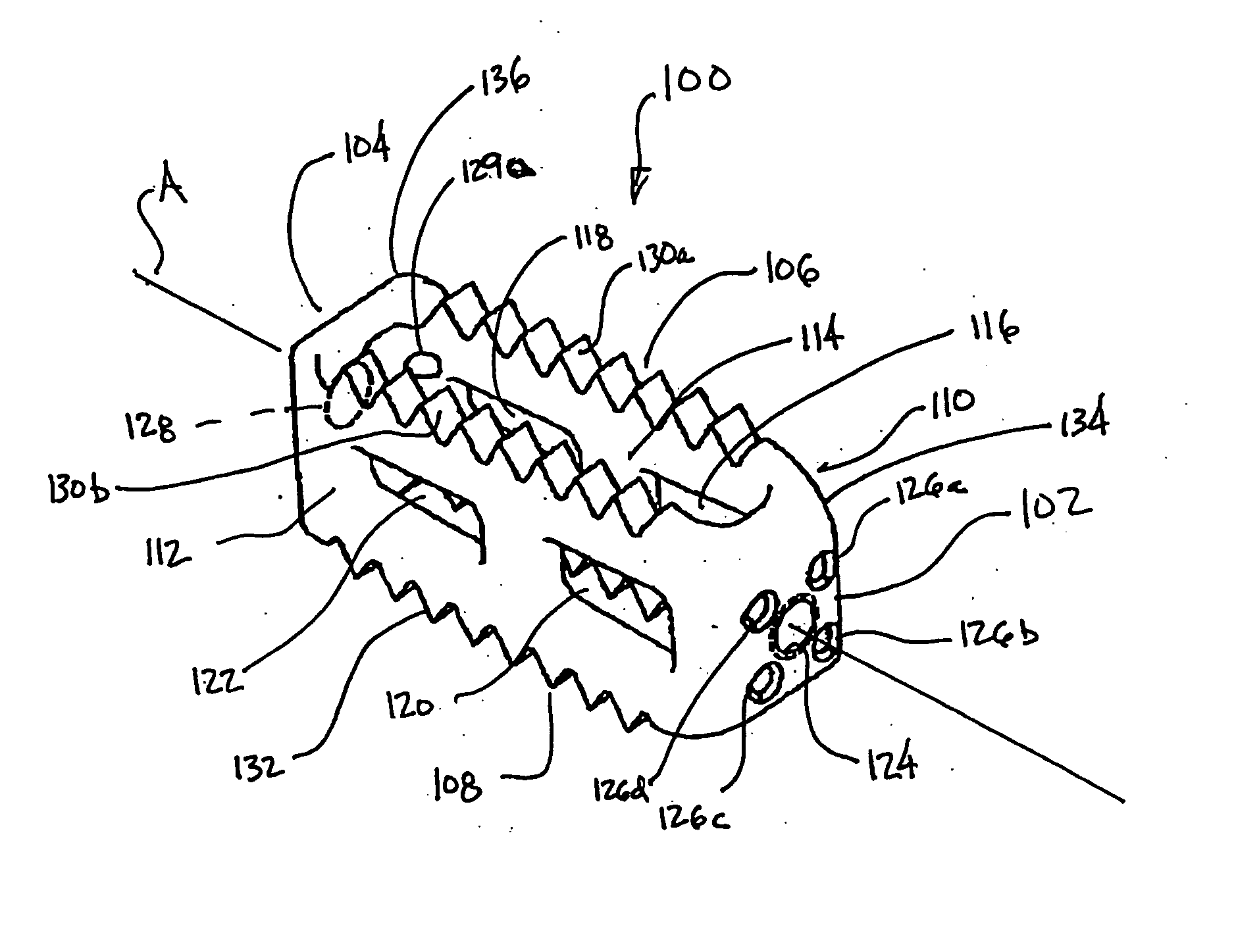
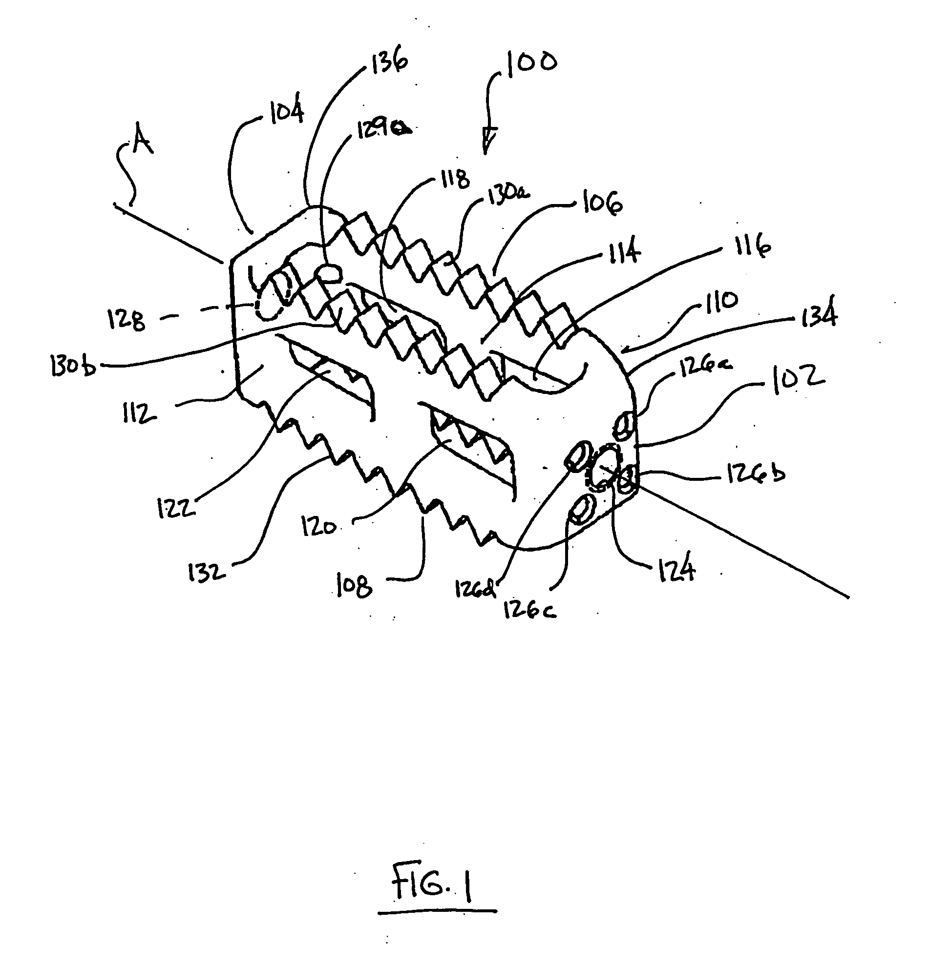
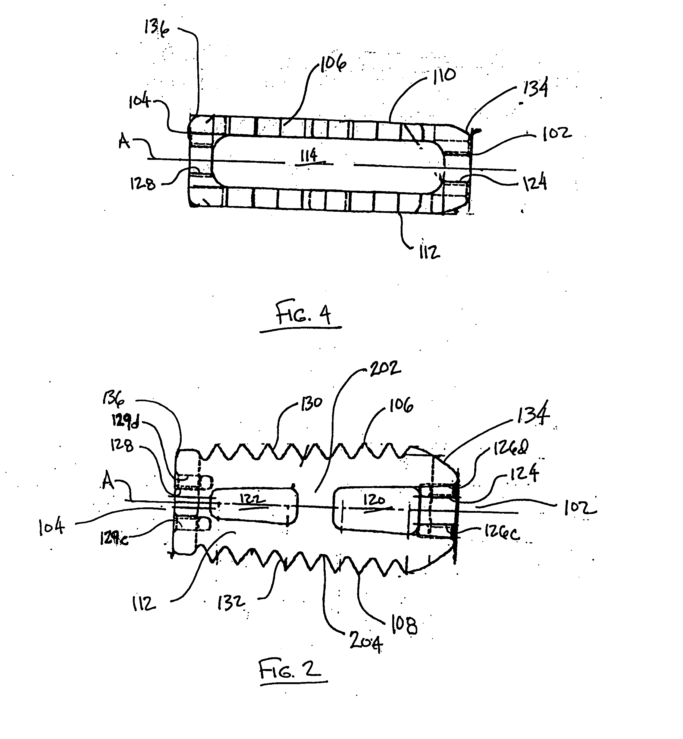
[0027] Disclosed herein is a prosthetic implant 100 that may be placed into a patient's spinal column from both the posterior side of the spinal column and the anterior side of the spinal column. Further, the prosthetic implant 100 disclosed herein is wedged shape to help maintain the curvature of the spinal column of the patient after placement of the prosthetic implant 100 between two vertebrae. The prosthetic implant 100 at the present disclosure further includes serrations on the top 130a-b and bottom 132a-b sides at the prosthetic implant 100 to allow purchase or digging into the bone of the vertebrae of the prosthetic implant 100 during and after placement. Further, the serrations 130a-b, 132a-b of the prosthetic implant 100 on the top of each side are positioned in a direction that substantially opposes the direction of the serrations on the bottom of the side to help to negate any migration of the prosthetic implant 100 out of the placed location in the spinal column. Furthe...


PUM


Abstract

Disclosed herein is a prosthetic implant, a tool assembly for positioning the prosthetic implant, and a method of placing a prosthetic implant. The prosthetic implant includes an anterior end and an opposite, smaller, posterior end. Left and right side portions attach the anterior end to the posterior end. Each of the left and right side portions includes serrations on the top and bottom. The serrations on the top are directed substantially opposite the direction of the serrations on the bottom. Adjacent serrations can be separated by a radius. The implant includes tooling apertures for receiving corresponding portions of a tool assembly. The tool assembly includes an inner tool and an outer tool. The inner tool can engage the implant and can seat the outer tool to the implant. The outer tool can be used to exert a rotational force to the implant to rotate the implant to a desired orientation.

Description

FIELD OF THE DISCLOSURE [0001] The present disclosure relates generally to prosthetic implants and, more specifically, to an intervertebral implant used for spinal fusion. BACKGROUND OF THE DISCLOSURE [0002] Prosthetic implants inserted into the spine have been useful in treating patients with damaged or degenerated invertebral discs. Typically, spinal prosthetic implants are inserted from the posterior side of the spinal column. To insert a prosthetic implant from the posterior side is challenging since the invertebral space in the spinal column is smaller in the posterior side of the spinal column versus the anterior side. Some methods of insertion require the surgeon to open the area of insertion of the spinal column by distracting between pedicle screws above and below and then subsequently compressing between the screws once the prosthetic implant is in place. Another method may include distracting on the vertebrae themselves with a thin long tipped distracter which is inserted...

Claims


Application Information

Patent Timeline
IPC IPC(8): A61F2/44A61F2/46A61B17/88
CPCA61F2/447A61F2310/00179A61F2002/30112A61F2002/30166A61F2002/30235A61F2002/30266A61F2002/30601A61F2002/30772A61F2002/30904A61F2002/4475A61F2002/448A61F2002/4627A61F2002/4629A61F2230/0004A61F2230/0028A61F2230/0069A61F2230/0082A61F2310/00011A61F2310/00161A61F2/4611A61F2002/30593
Inventor ALEXANDER, GERALD JOHNNEARY, DOUGLAS
Owner SPINEWORKS
Why Eureka
Try Eureka