
Air purifier

Inactive Publication Date: 2007-01-04
SAMSUNG ELECTRONICS CO LTD
View PDF10 Cites 32 Cited by
  • Summary
  • Abstract
  • Description
  • Claims
  • Application Information

AI Technical Summary

Benefits of technology

[0011] The present general inventive concept provides an air purifier, designed to allow dust attached to a dust filter to be conveniently and rapidly removed from the dust filter without taking the dust filter out of the air purifier. The present invention general inventive also provides an air purifier, designed to prevent electrostatic force from occurring on a surface of the dust filter and to allow the dust to be easily detached from the dust filter.
[0013] The foregoing and / or other aspects of the present general inventive concept are also achieved by providing an air purifier, comprising a housing, a dust filter and a blowing fan equipped within the housing, a vibrating member disposed adjacent the dust filter, and a plurality of vibration motor assemblies provided on the vibrating member and disposed to vibrate in different directions therein to effectively remove dust attached to the dust filter.
[0020] A surface of the dust filter may be coated to prevent static electricity from accumulating thereon to easily remove dust therefrom.

Problems solved by technology

However, when the conventional air purifier is used for a predetermined period of time or longer, a surface of the dust filter is covered with dust and becomes blocked, so that an amount of air that can pass through the dust filter of the air purifier is significantly decreased, and severe noise is generated by the air purifier.
As a result, the conventional air purifier has drawbacks in that the dust filter should be periodically taken out of the air purifier for maintenance (to remove the dust collected on the dust filter), creating an inconvenience.
Additionally, if the dust is not periodically removed from the dust filter, a lifetime of the dust filter decreases.
In particular, for the conventional air purifier described above, dust particles are not easily detached from the dust filter due to electrostatic force generated on the surface of the dust filter.
Thus, it is very difficult to remove the dust particles from the dust filter.
Furthermore, some of the dust particles are often stuck on the dust filter, and are not detached from the dust filter, thereby deteriorating the filtering performance of the dust filter while significantly increasing a load of the blowing fan.

Method used


Image

  • Air purifier
  • Air purifier
  • Air purifier

Examples


Embodiment Construction

[0031] Reference will now be made in detail to the embodiments of the present general inventive concept, examples of which are illustrated in the accompanying drawings, wherein like reference numerals refer to the like elements throughout. The embodiments are described below in order to explain the present general inventive concept by referring to the figures.

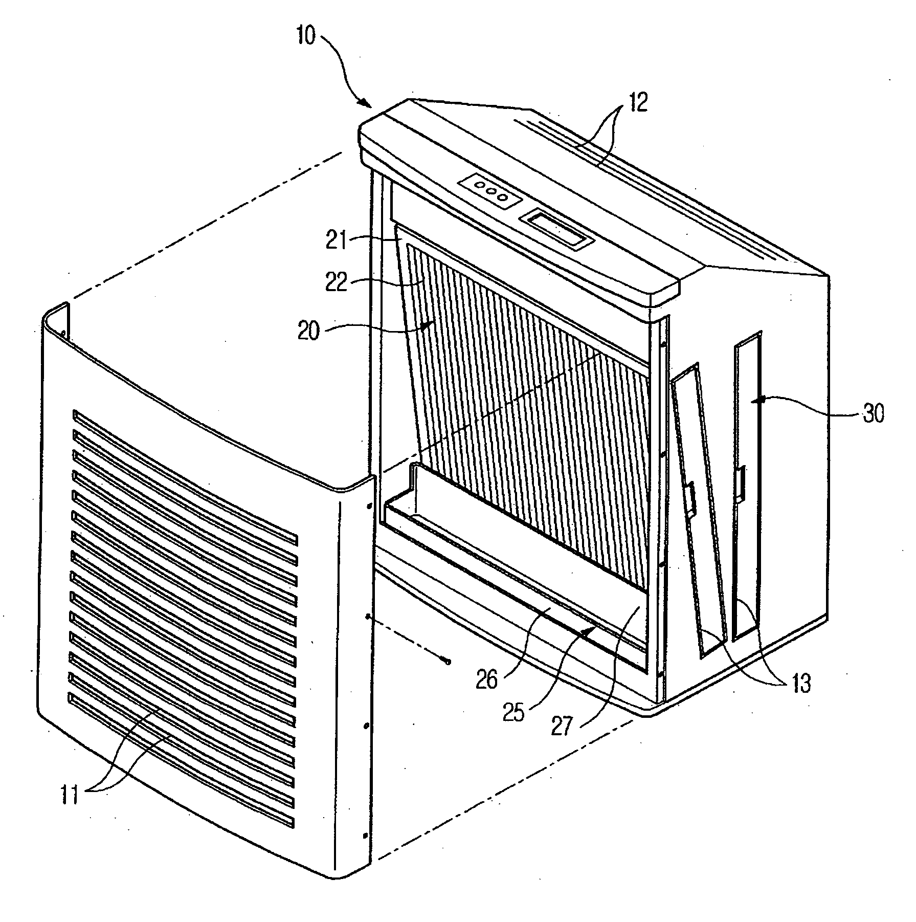
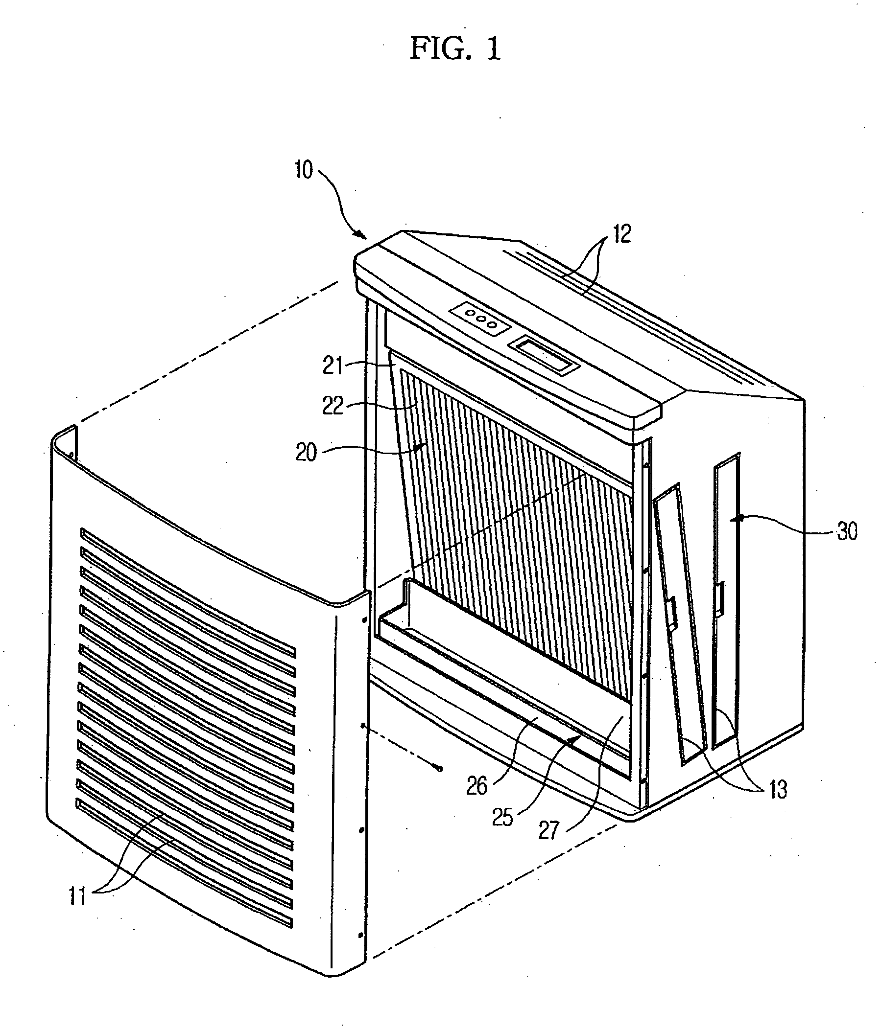
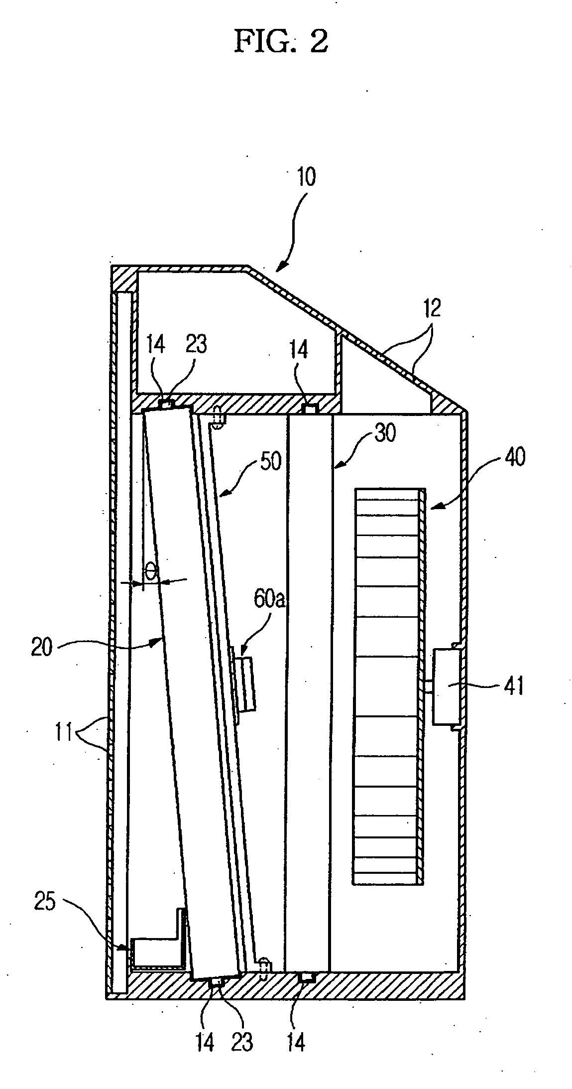
[0032]FIG. 1 is a front perspective view illustrating an air purifier with a dust filter 20 slanted therein according to an embodiment of the present general inventive concept. FIG. 2 is a longitudinal cross-sectional view illustrating the air purifier with a vibrating member 50 and a plurality of vibration motor assemblies 60a (and 60b, see FIG. 3) disposed on a rear portion of the dust filter 20, and FIG. 3 is a perspective view illustrating the vibrating member 50 and the plurality of vibration motor assemblies of the air purifier illustrated in FIG. 2. In the following description of the air purifier, according to the pres...


PUM

PropertyMeasurementUnit
Angleaaaaaaaaaa
Angleaaaaaaaaaa
Forceaaaaaaaaaa

Abstract

An air purifier includes a vibrating member disposed adjacent to a dust filter, and first and second vibration motor assemblies disposed longitudinally and transversely on the vibrating member, respectively, to cause the vibrating member to vibrate in several directions. Each of the vibration motor assemblies has a case fixed to the vibrating member, a vibrating motor disposed within the case, and a cover to close the case. The vibration motor includes a stator fitted to a sheet member within the case, a rotor rotatably disposed within the stator, and an eccentric shaft connected to the rotor to generate vibration via an eccentric rotation of the eccentric shaft.

Description

CROSS-REFERENCE TO RELATED APPLICATIONS [0001] This application claims the benefit under 35 U.S.C. §119 from Korean Patent Application No. 2005-58081, filed on Jun. 30, 2005 in the Korean Intellectual Property Office, the disclosure of which is incorporated herein in its entirety by reference. BACKGROUND OF THE INVENTION [0002] 1. Field of the Invention [0003] The present general inventive concept relates to an air purifier, and more particularly, to an air purifier designed to allow dust that collects on a dust filter to be removed conveniently, rapidly and automatically. [0004] 2. Description of the Related Art [0005] Generally, an air purifier comprises a filter unit to purify air and a blowing fan to forcibly blow the air within a housing. When the air purifier is operated to purify indoor air, the blowing fan forces the indoor air to pass through the filter unit to filtrate dust, odor and bacteria contained in the air that passes through the filter unit, and then forces the pur...

Claims


Application Information

Patent Timeline
IPC IPC(8): B01D46/04F24F8/108F24F8/90
CPCB01D46/0005B01D46/0023B01D46/0038F24F2003/1639B01D46/10F24F3/1603F24F2003/1614B01D46/0075F24F8/90F24F8/108F24F8/10B01D46/76B01D46/62B01D46/42Y02A50/20
Inventor PARK, CHAN JUNGKIM, YOUNG SAENG
Owner SAMSUNG ELECTRONICS CO LTD
Learn More