
Eureka
For R&D, Eureka makes reading and utilizing patents & technical documents easy.
Eureka AIR
Designed for self-driven R&D workflows. Generate viable solutions, solve complex R&D challenges, empower your innovation with AI.

Eureka Materials
Designed for material experts only. Revolutionize your material R&D, from search, analyze, to developing new materials.

TechResearch
Generate reliable direction feasibility study reports for your R&D in just a few steps.

TechSeek
Discover and master advanced knowledge NOW. Basics, ideas, possibilities, all at once.

TechMind
As an expert in R&D Theories, TechMind can generates customized viable solutions instantly.

TechRisk
Analyze your overall solution with one click, know your potential R&D risks in advance.

TechMonitor
Get weekly tech updates, stay abreast of the latest tech innovations and key insights.
Gun rack
a gun rack and gun technology, applied in the field of storage devices, can solve the problem that the rack cannot accommodate inverted (barrel-down) guns
- Summary
- Abstract
- Description
- Claims
- Application Information
AI Technical Summary
Benefits of technology
Problems solved by technology
Method used
Image

Examples
first embodiment
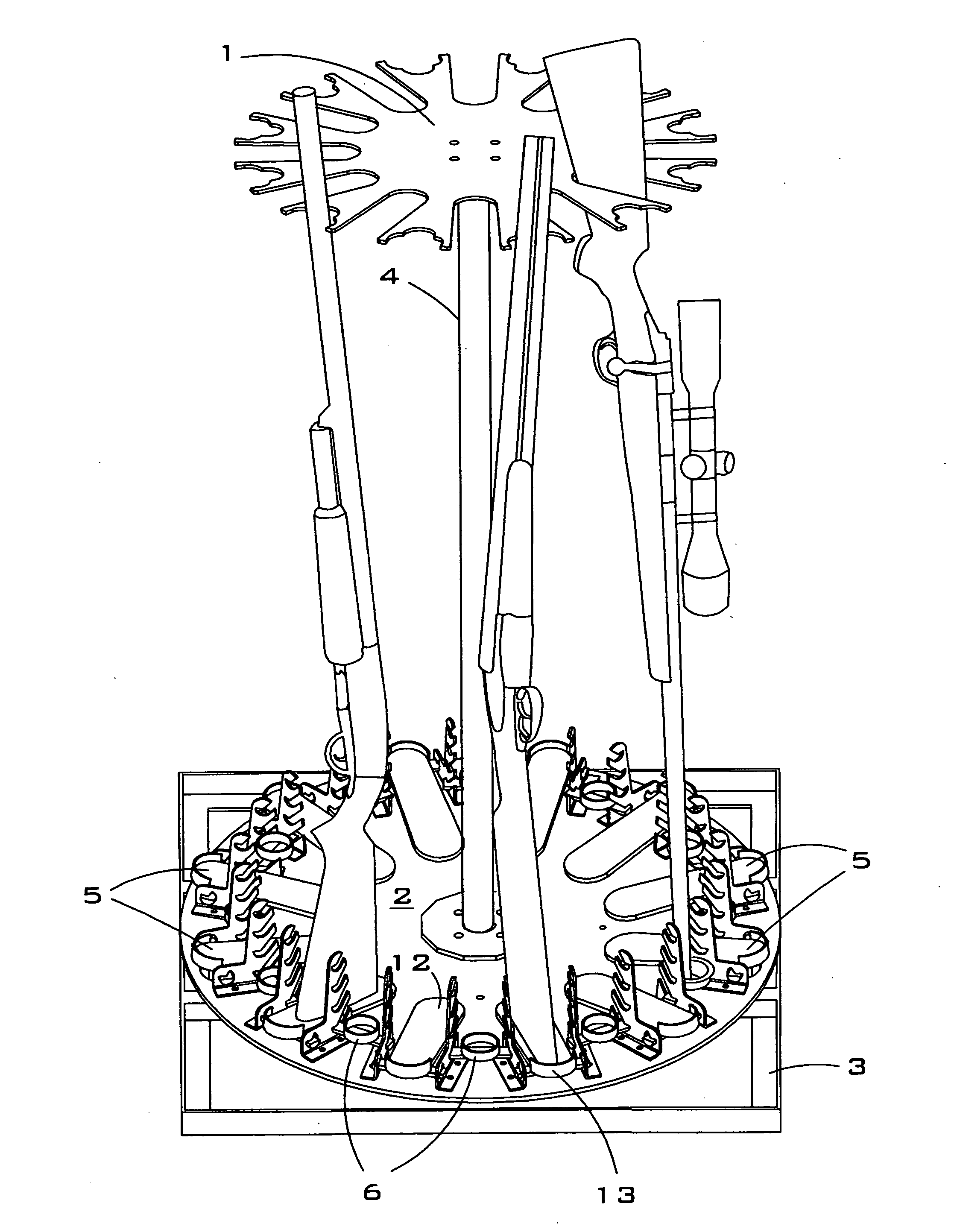
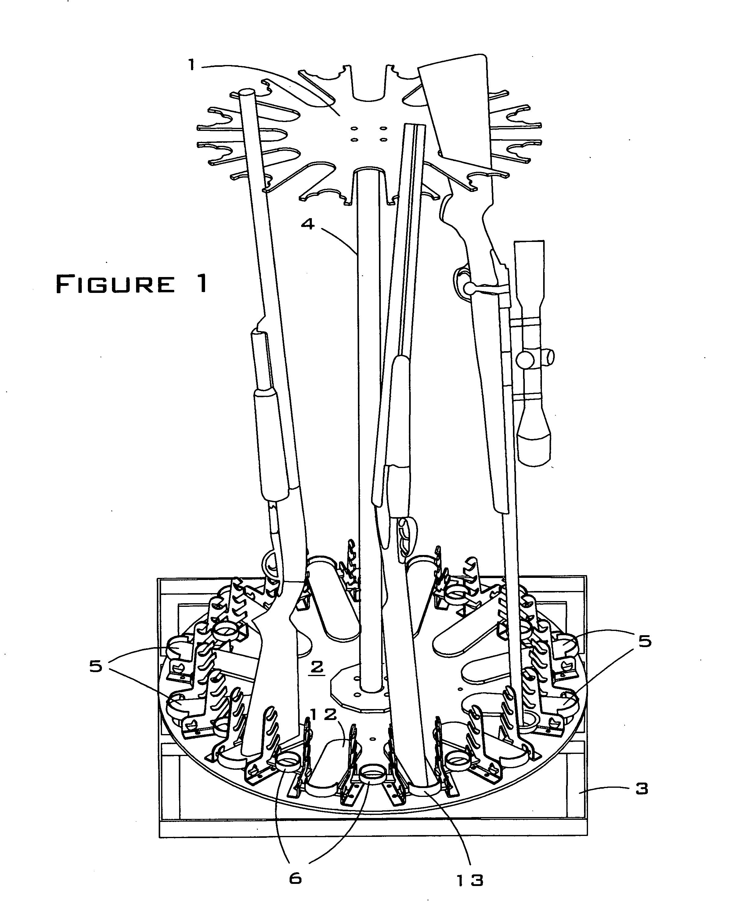
[0097]FIG. 1 is a perspective view of the gun rack of the present invention. This figure shows the top receiver disc 1, the bottom receiver disc 2, the base unit 3 and the shaft 4. It also shows the swivel shoes 5, which hold the gun butts, and the barrel receivers 6, which hold the gun barrels. As shown in greater detail in FIGS. 7 and 9, the barrel receiver brackets 7 support both the swivel shoes 5 and the barrel receivers 6 and allow both the swivel shoes 5 and the barrel receivers 6 to pivot. In this embodiment, the guns are placed on the rack in alternating positions, butt to barrel. This placement is possible due to the alternating swivel shoes and barrel receivers on the bottom receiver disc 2, as well as the cutouts on the top receiver disc for both gun stocks and barrels (discussed more fully in connection with FIG. 3).
[0098] In FIG. 1, the one barrel receiver 6 that is shown holding a gun barrel is also shown with a protective insert 8, which fits inside the barrel receiv...
second embodiment
[0111]FIGS. 15-20 illustrate the present invention. In this embodiment, the barrel receivers are not vertically adjustable. In order to compensate for the adjustability lost by eliminating the vertical adjustability of the barrel receivers, the top receiver disc is split in two, and one half of the top receiver disc is positioned lower than the other half in order to accommodate guns of different lengths.
[0112]FIG. 15 is a perspective view of the second embodiment of the gun rack of the present invention. This figure shows the top receiver disc 1, the bottom receiver disc 2, and a middle receiver disc 24. The middle receiver disc 24 is positioned on the shaft 4 between the top receiver disc 1 and bottom receiver disc 2, but preferably closer to the top disc 2. The rest of the gun rack is the same as shown in the first embodiment, except that the barrel receiver brackets 7 are replaced with swivel shoe brackets 25, shown in great detail in FIG. 20. The barrel receivers 6 are immovabl...
third embodiment
[0119]FIG. 22 is a side view of the gun rack of the present invention. This figure shows the top receiver disc 1, the shaft 4, the bottom receiver disc 2, the base unit 3, the swivel shoes 5, and the swivel shoe brackets 25.
[0120]FIG. 23 is a top view of the third embodiment of the gun rack of the present invention. This figure shows the top receiver disc 1, the bottom receiver disc 2, the swivel shoes 5, and the swivel shoe brackets 25. The vertical orientation of the swivel shoes to the cutouts 10 is the same as in the first and second embodiments.
[0121]FIG. 24 is a top view of the top receiver disc of the third embodiment of the gun rack of the present invention. This figure shows more clearly the cutouts 10 in the top receiver disc 1. FIG. 25 is a top view of the bottom receiver disc of the third embodiment of the gun rack of the present invention. This figure shows the bottom receiver disc 2, the swivel shoes 5, and the swivel shoe brackets 25.
[0122]FIGS. 26-30 relate to a pi...
PUM
 Abstract
Description
Claims
Application Information
 - R&D Engineer
- R&D Manager
- IP Professional
- Industry Leading Data Capabilities
- Powerful AI technology
- Patent DNA Extraction
Browse by: Latest US Patents, China's latest patents, Technical Efficacy Thesaurus, Application Domain, Technology Topic, Popular Technical Reports.
© 2024 PatSnap. All rights reserved.Legal|Privacy policy|Modern Slavery Act Transparency Statement|Sitemap|About US| Contact US: help@patsnap.com