Filter lip seal and method

Inactive Publication Date: 2007-01-04
FILTRAN LLC
View PDF8 Cites 4 Cited by
  • Summary
  • Abstract
  • Description
  • Claims
  • Application Information

AI Technical Summary

Benefits of technology

[0008] In some aspects of some embodiments of the present invention, an improved lip seal and sealing method is provided. It would be desirable to have an improved lip seal and sealing method for sealing around

Problems solved by technology

During the life of a transmission, however, the filter may sometimes need to be replaced.
This filter removal step has presented several challenges with respect to the lip seal.
This problem is exacerbated by the fact that the outside of a filter neck is typically very smooth, due to the fact that the filter neck is usually an injection molded part.
The problem of the lip seal frictionally being left behind in the inlet, after sliding off the filter neck is also driven in part by the fact that the filter neck, which is usually an injection molded plastic part, tends to shrink due to the heat cycles experienced during its life.
This solution is not always desirable, however, as it can cause extra efforts or difficulties with respect to the injection molding process for the filter casing itself.
T

Method used


Image

  • Filter lip seal and method
  • Filter lip seal and method
  • Filter lip seal and method

Examples


Example

[0020] In some embodiments of the present invention, an improved lip seal and sealing method is provided for sealing around the outside of a neck that is inserted into a larger bore. In some embodiments an element is added to the seal that at least to some extent enhances the retention of the seal on the neck when the seal is removed from the bore. Preferred embodiments of the invention will now be further described with reference to the drawing figures in which like reference numerals refer to like parts throughout.

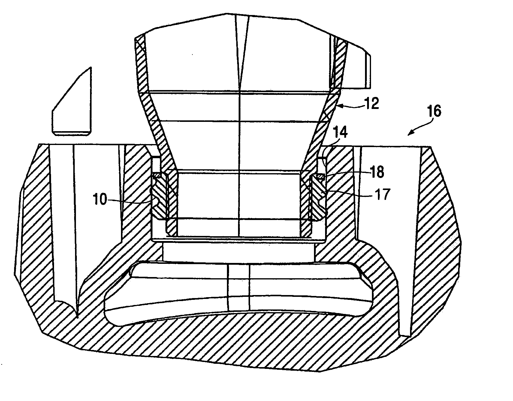
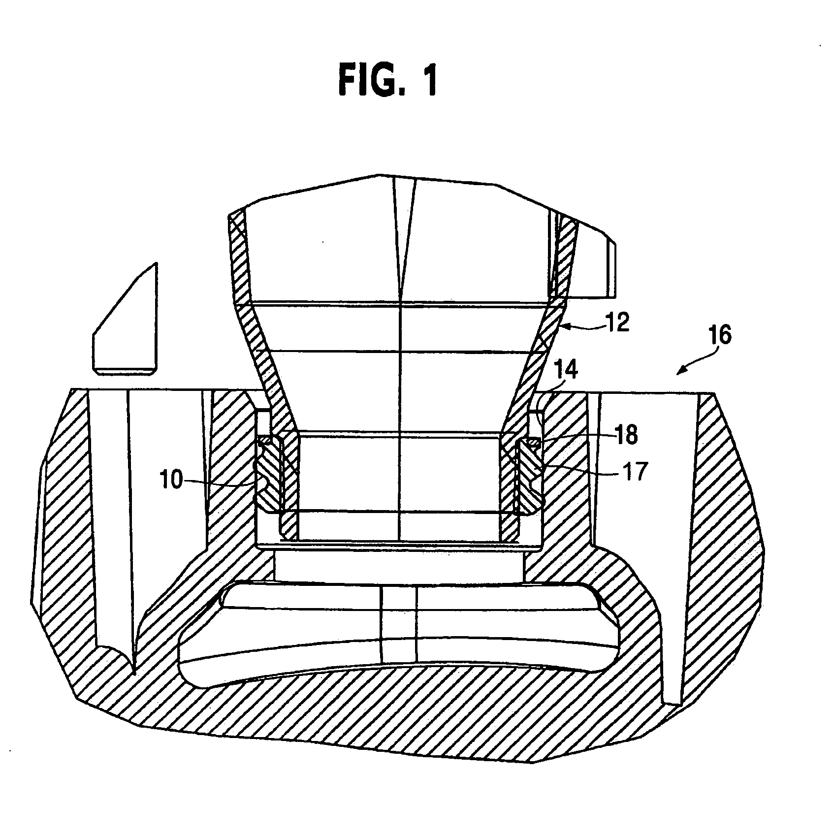
[0021]FIG. 1 illustrates a lip seal 10 according to a preferred embodiment of the present invention. The lip seal 10 is shown in an installed configuration in a layout view. The lip seal 10 provides sealing between the outside of a neck 12 of a transmission filter and an inlet bore 14 of a transmission component 16. The neck 12 is typically an injection molded feature, which may be integral with an outer casing of a transmission or other fluid filter. The transmission c...


PUM


Abstract

A lip seal has an internal spring element disposed in an elastomeric ring. The spring element has a cervical angle cross-sectional with inwardly directed angled fingers

Description

FIELD OF THE INVENTION [0001] The present invention relates generally to the field of resilient seals, and more particularly pertains to the sealing of the an item, such as for example a transmission filter having a neck, within a bore of a piece of machinery, such as for example a transmission. More particularly, the invention in some aspects pertains to a seal referred to as a “lip seal”. BACKGROUND OF THE INVENTION [0002] There are wide variety of circumstances in which a compressible resilient lip seal is desired. One of these applications is the connection of a fluid filter, such as for example a transmission filter, with respect to a bore or orifice in a device such as for example a vehicular transmission. In the case of a transmission filter, the filter typically has a neck extending from the filter, which typically provides either the inlet or outlet of fluid with respect to the filter casing. This neck is typically inserted into a bore or socket that is part of the transmis...

Claims


Application Information

Patent Timeline
IPC IPC(8): F16J15/32
CPCF16J15/061F16J15/125F16J15/104F16J15/34
Inventor PEET, C. ALANMARKOV, IGORKHALIL, IBRAHIM
Owner FILTRAN LLC
Why Eureka
Try Eureka