Form and method and apparatus for making a form

Inactive Publication Date: 2008-06-05
SMOLJO DOUG
View PDF37 Cites 0 Cited by
  • Summary
  • Abstract
  • Description
  • Claims
  • Application Information

AI Technical Summary

Benefits of technology

[0007]Preferably, the groove is undercut and the tongue has an enlarged head to enhance the retention within the groove. As a further prefe

Problems solved by technology

However, the storage of such tubes is difficult since they cannot be easily stacked one on top of the other due to their circular nature and is also in efficient as one tube occupies a large volume.
Although some ef

Method used


Image

  • Form and method and apparatus for making a form
  • Form and method and apparatus for making a form
  • Form and method and apparatus for making a form

Examples


Example

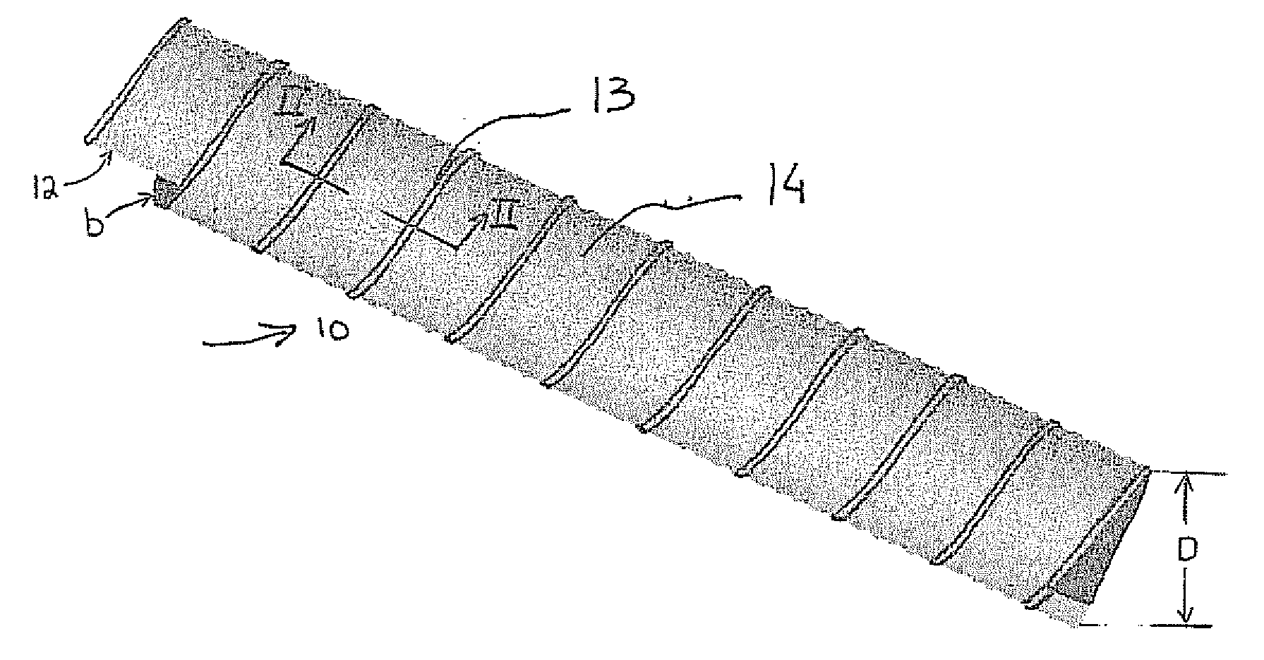
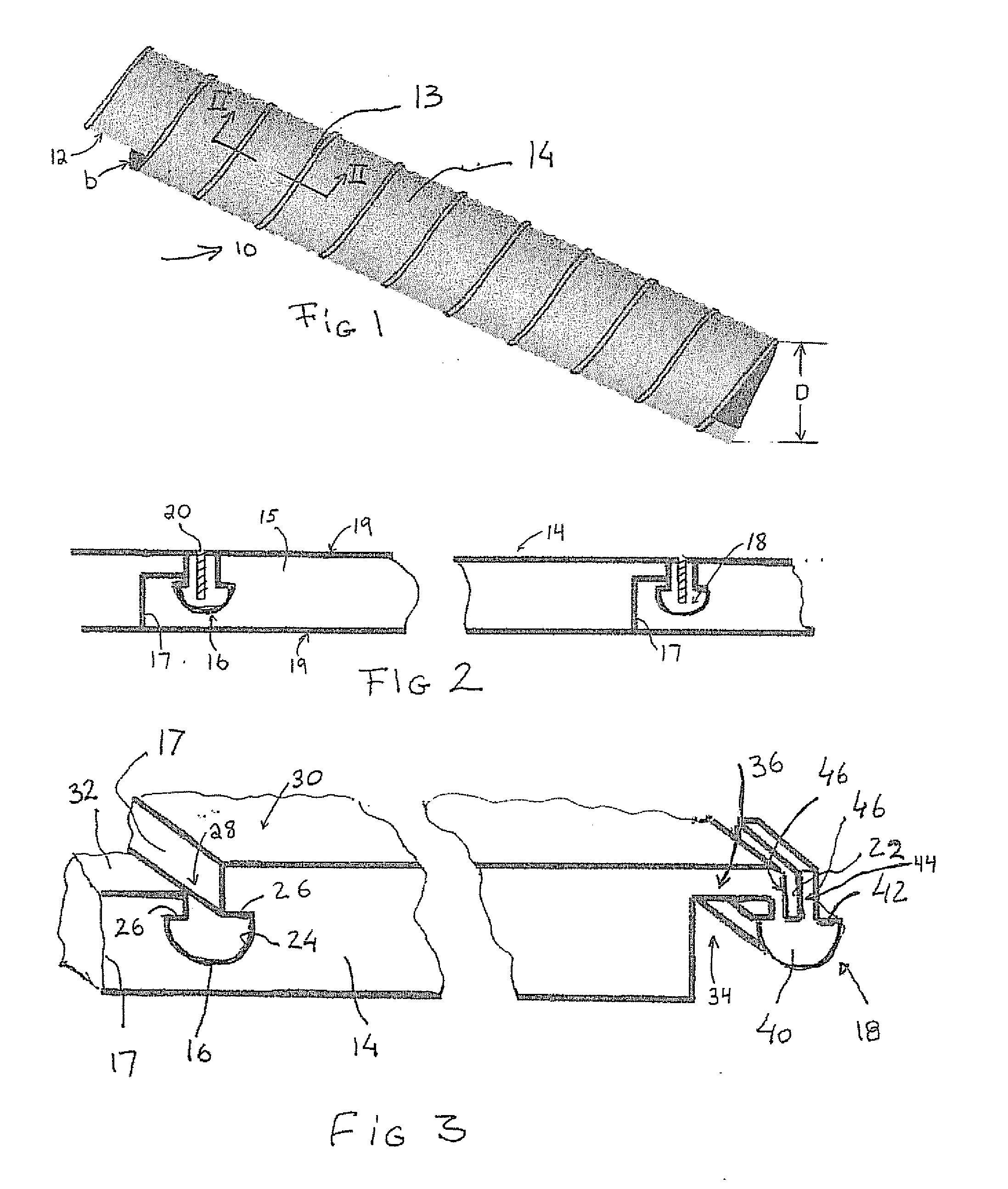
[0017]Referring therefore to FIG. 1, a form indicated by reference numeral 10 has a cylindrical wall 12 formed from a helically wound strip 14. Abutting edges of the strip 14 are interconnected by a tongue and groove joint generally indicated at 13 and seen in greater detail in FIGS. 2 and 3. The tube 10 is formed to a nominal diameter D which typically will range between 6 and 12 inches. The wall 14 has a nominal thickness indicated at b that is chosen so as to be sufficiently flexible to accommodate the radius of curvature required whilst withstanding the pressure that may be exerted when used as a form. A nominal thickness of ⅛″ is believed to be appropriate.

[0018]Referring therefore to FIG. 2, the strip 14 has a body 15 with lateral edges 17 and oppositely directed faces 19. Complementary formations in the form of a groove 16 and a tongue 18 are formed on opposite lateral edges 17. The strip 14 is preferably made from a plastics material which is flexible so as to be able to be ...


PUM

PropertyMeasurementUnit
Flexibilityaaaaaaaaaa
Separationaaaaaaaaaa

Abstract

A concrete form having a tubular body formed from a flexile strip wound helically in successive passes to define a wall of the form. The adjacent edges of the strip being releasably engaged with one another to exhibit axial separation of the strip.

Description

[0001]This application claims priority from U.S. Provisional Patent Application No. 60 / 831,226 filed on Jul. 17, 2006.FIELD OF THE INVENTION[0002]The present invention relates to forms for moulding material and to methods and apparatus of creating such form-s.SUMMARY OF THE INVENTION[0003]Forms are used in a variety of applications to provide temporary containment for mouldable materials. A typical application of such form is in the pouring of concrete where it is necessary to hold the concrete in the desired shape until it has set. A commonly used form is a cylindrical tube that is used to establish pillars or piers to support additional structure. Typically, these tubes, commonly known by the trademark “Sonotube” are formed from layers of paper material that are helically wound and glued to one another during forming to produce a rigid structure. The tubes have sufficient strength to support concrete and, upon setting, the layers of the tube can be removed to expose the concrete.[...

Claims


Application Information

Patent Timeline
IPC IPC(8): E04G13/02
CPCB31C3/00Y10T29/49915Y10T428/24008E04G13/021
Inventor SMOLJO, DOUG
Owner SMOLJO DOUG
Why Eureka
Try Eureka