Methods and devices for networking blade servers

a blade server and networking technology, applied in the field of communication networks, can solve the problems of data center scaling limit, difficult maintenance of division of responsibility, and increase of administrative overhead

Active Publication Date: 2007-01-04
CISCO TECH INC
View PDF8 Cites 76 Cited by
  • Summary
  • Abstract
  • Description
  • Claims
  • Application Information

AI Technical Summary

Benefits of technology

[0013] Some embodiments of the present invention provide blade servers having components that function as switches in the data plane, but do not function as normal switches in the control plane and do not have a separate Domain_ID. Such components may sometimes be referred to herein as “blade switches” or “satellite switches” even though the bla

Problems solved by technology

It can readily be seen that such limitations are causing data centers to quickly reach the total FC switch scaling limit.
In addition to the foregoing issues, including additional switches creates additional administrative overhead.
With the blade server architecture, since switches and servers are in the same chassis, this division of responsibility is difficult to maintain.
However,

Method used


Image

  • Methods and devices for networking blade servers
  • Methods and devices for networking blade servers
  • Methods and devices for networking blade servers

Examples


Embodiment Construction

[0045] In this application, numerous specific details are set forth in order to provide a thorough understanding of the present invention. It will be obvious, however, to one skilled in the art, that the present invention may be practiced without some or all of these specific details. In other instances, well known process steps have not been described in detail in order not to obscure the present invention.

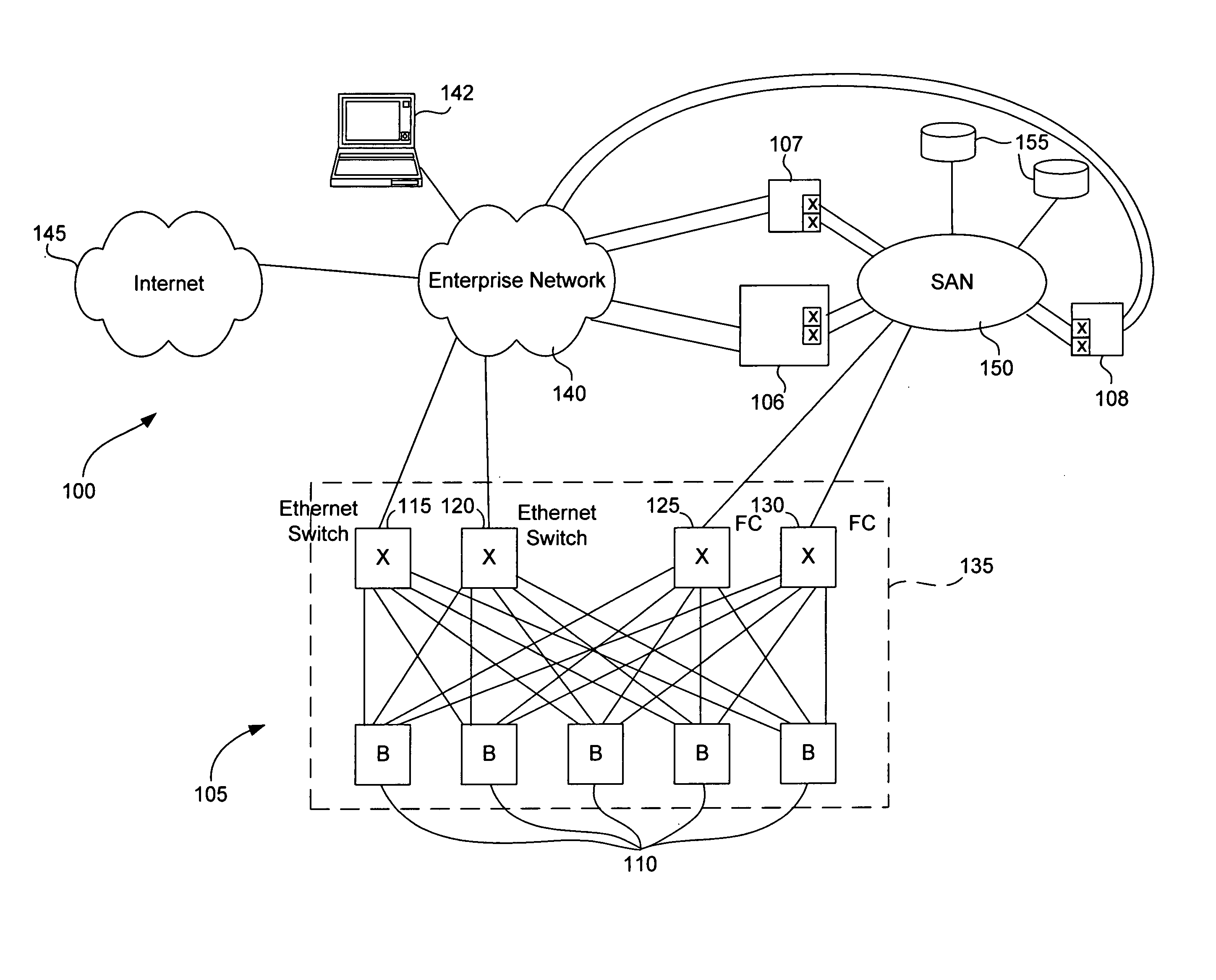
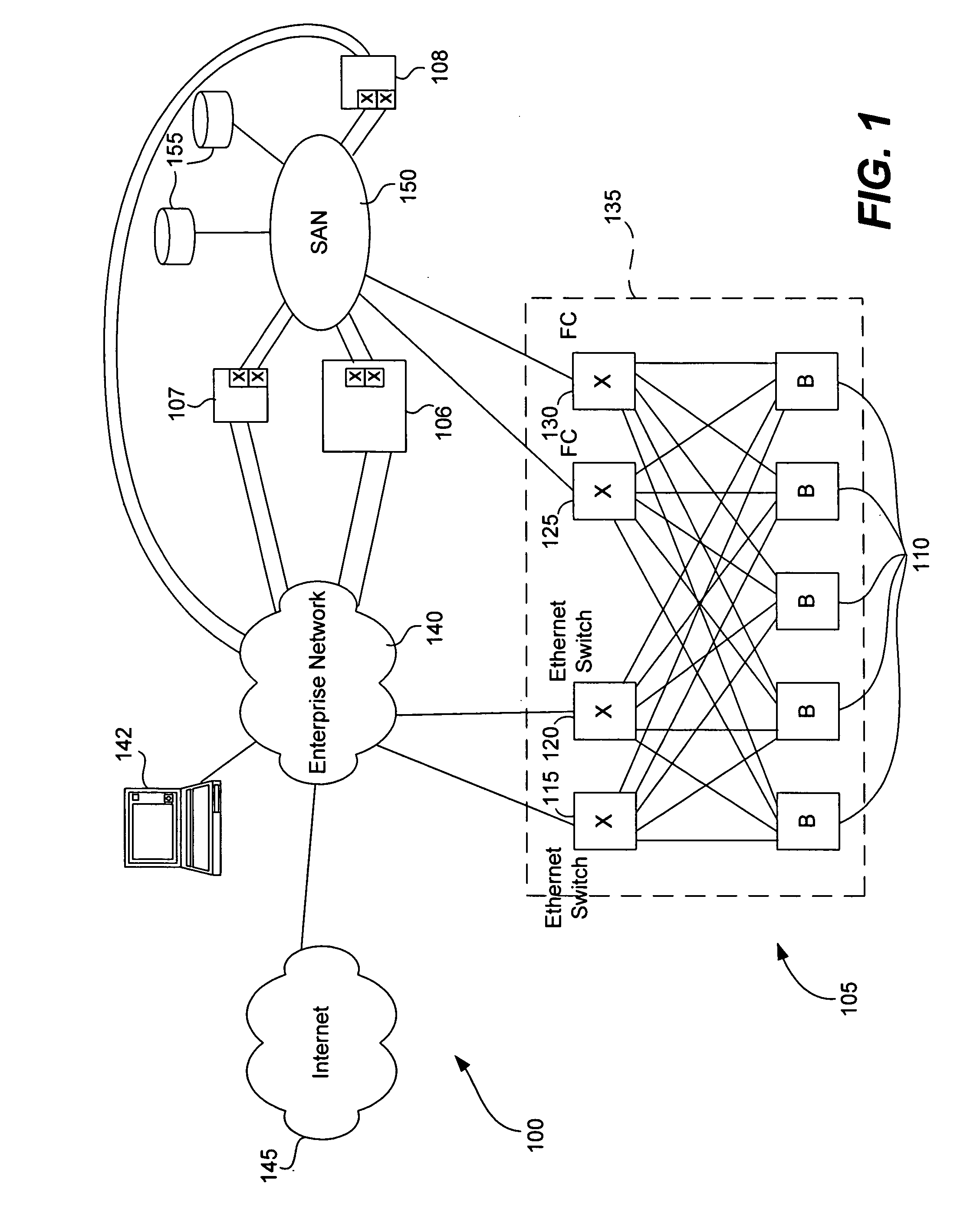
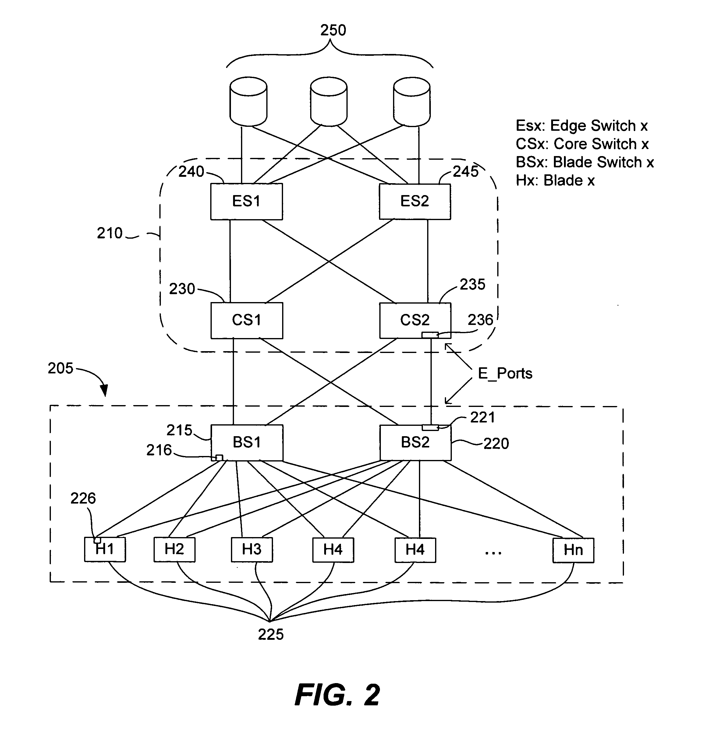
[0046]FIG. 2 is a simplified network diagram that illustrates conventional blade server 205 connected with SAN 210. Blade server 205 includes switches 215 and 220, both of which are redundantly connected to each of N blades 225. SAN 210 includes core switches 230 and 235, both of which are redundantly connected to switches 215 and 220. SAN 210 also includes edge switches 240 and 245, both of which are redundantly connected to each of the core switches and storage devices 250.

[0047] According to the FC protocol, E_Ports connect switches to other switches. Therefore, port 221 of ...


PUM


Abstract

Some embodiments of the present invention provide blade servers having blade switches that function as switches in the data plane, but do not have a Domain_ID. Control plane switching functions are performed by a fabric switch (e.g., a core switch) to which the blade server is attached. A fabric switch to which a blade switch is attached may perform address assignment functions for blades of the blade server. The blade switch preferably converts FLOGI requests to FDISC requests that are forwarded to an attached fabric switch. Some implementations provide for the multiple fabric switches, all of which are configured for communication with at least one blade switch, to establish and maintain the state of a virtual Domain_ID.

Description

BACKGROUND OF THE INVENTION [0001] 1. Field of the Invention [0002] The present invention relates to communication networks. More particularly, the present invention relates to the use of blade servers in communication networks, including but not limited to Fibre Channel (“FC”) networks. [0003] 2. Description of the Related Art [0004] A recent trend in the data center is to deploy blade servers. Blade servers generally have a modular chassis and a set of central processing unit (“CPU”) blades plugged into that chassis. In addition to CPU blades, there are typically 2 or more network interface blades. Some of these network interface blades are used for FC connectivity, generally to a storage area network (“SAN”), and some of them are for Ethernet connectivity. The benefits of blade servers include greater rack density, simplified interconnect, and lower cost. [0005] The deployment of a typical blade server is illustrated in FIG. 1. Blade server 105 includes blades 110, each of which ...

Claims


Application Information

Patent Timeline
IPC IPC(8): H04L12/56H04L12/28
CPCH04L49/253H04L49/357H04L49/45H04L67/1002H04L67/1006H04L67/1034H04L49/552H04L67/1001
Inventor EDSALL, THOMASDESANTI, CLAUDIO
Owner CISCO TECH INC
Why Eureka
Try Eureka