Rotate-to-advance catheterization system

a technology of rotating to advance and catheterization, which is applied in the field of apparatus and methods for catheterization and related treatments of the genitourinary and gastrointestinal passages of mammals, can solve the problems of failure to recognize the fundamental flaws and fundamental shortcomings of the basic push-to-advance technique, failure to resolve the critical features of the structure, and inability to realize the fundamental flaws and should be abandoned. , to achieve the effect of easier and more precise advancement and clearer view

Active Publication Date: 2007-01-04
OLYMPUS ENDO TECH AMERICA
View PDF54 Cites 100 Cited by
  • Summary
  • Abstract
  • Description
  • Claims
  • Application Information

AI Technical Summary

Benefits of technology

[0141] It should be appreciated that the system of the present invention can be rotated either manually (e.g., by the surgeon rotating the catheter by hand) or, alternatively, the system can be power driven. In a preferred form of the present invention, a powered drive may be used to rotate the catheter so as to allow an easier and more precise advancement of the catheter into the bodily passageway or retraction of the catheter from the bodily passageway.
[0142] In one preferred form of the present invention, a lavage system may be provided for clearing away debris

Problems solved by technology

There has been patent activity in the prior art indicating dissatisfaction with the push-to-advance methodology.
In all cases, these disclosures fail to recognize that the basic push-to-advance technique is fundamentally flawed and should be abandoned, and fail to resolve the critical features of structure necessary for rotational advancement as a substitute for the push-to-advance method.
Such disclosures likewise reveal a reliance on push-in methods, or an assumption that such structures can be pulled out without regard to the spiral features, again failing to recognize rotation as a viable substitute for pushing, and failing to resolve the critical features of structure necessary for effective rotational advancement.
As a further indication of the failure of the prior art to provide effective improvements to traditional push-in methods, there is no apparent indication among the produc

Method used


Image

  • Rotate-to-advance catheterization system
  • Rotate-to-advance catheterization system
  • Rotate-to-advance catheterization system

Examples


Embodiment Construction

[0189] To those skilled in the art, the invention admits of many variations and appellations in apparatus and methodology. By way of example, there is provided, in accordance with the present invention, a rotate-to-advance structure and methodology applicable to a range of medical devices that have heretofore relied entirely or substantially on a push-to-advance technique for penetration of bodily passages. Such devices include catheters, dilators, and occluders for mammalian genitourinary or gastrointestinal passages such as the urethra or ureter for the usual purposes associated with such devices where no incising or rupture of passage walls or membranes is intended.

Catheters

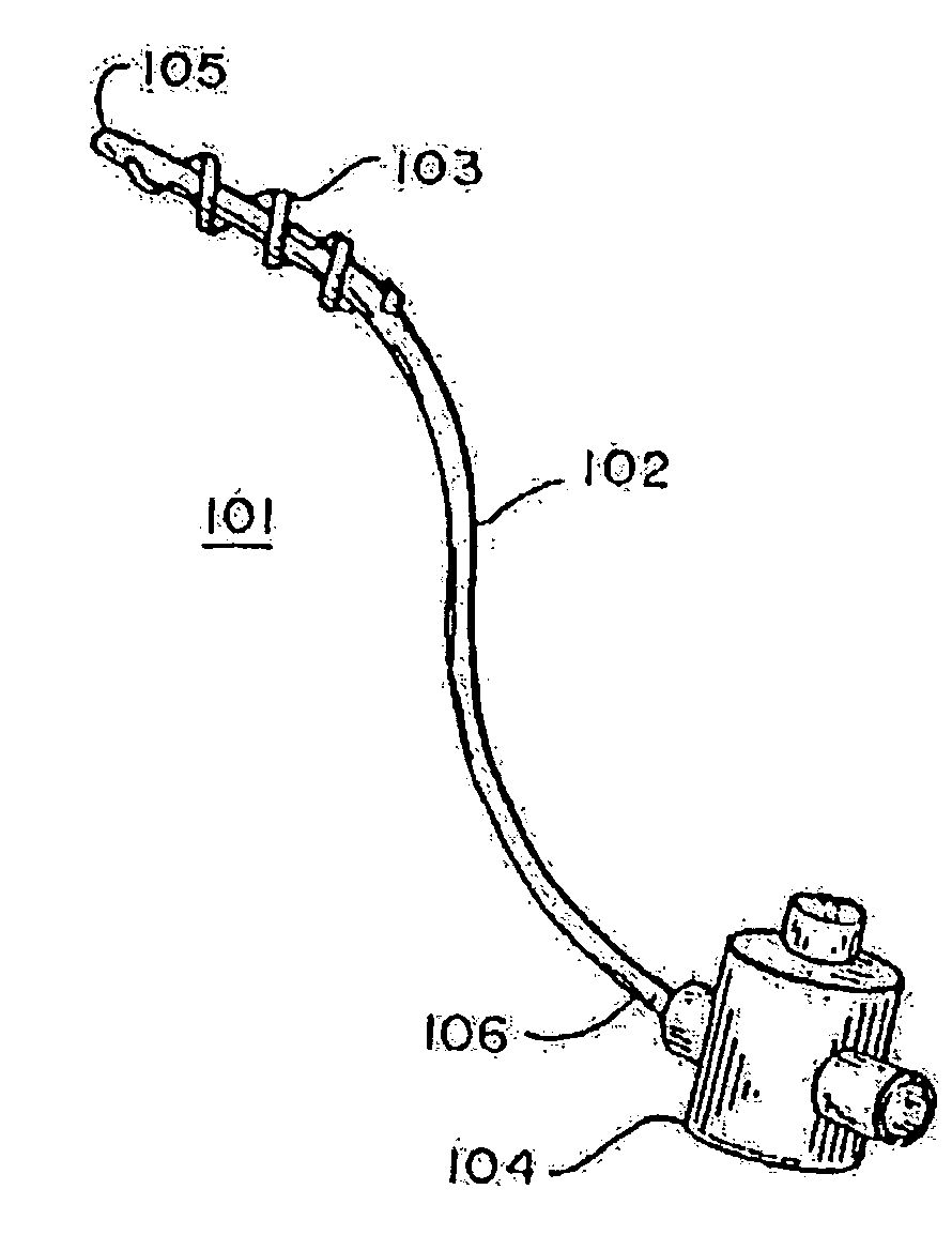
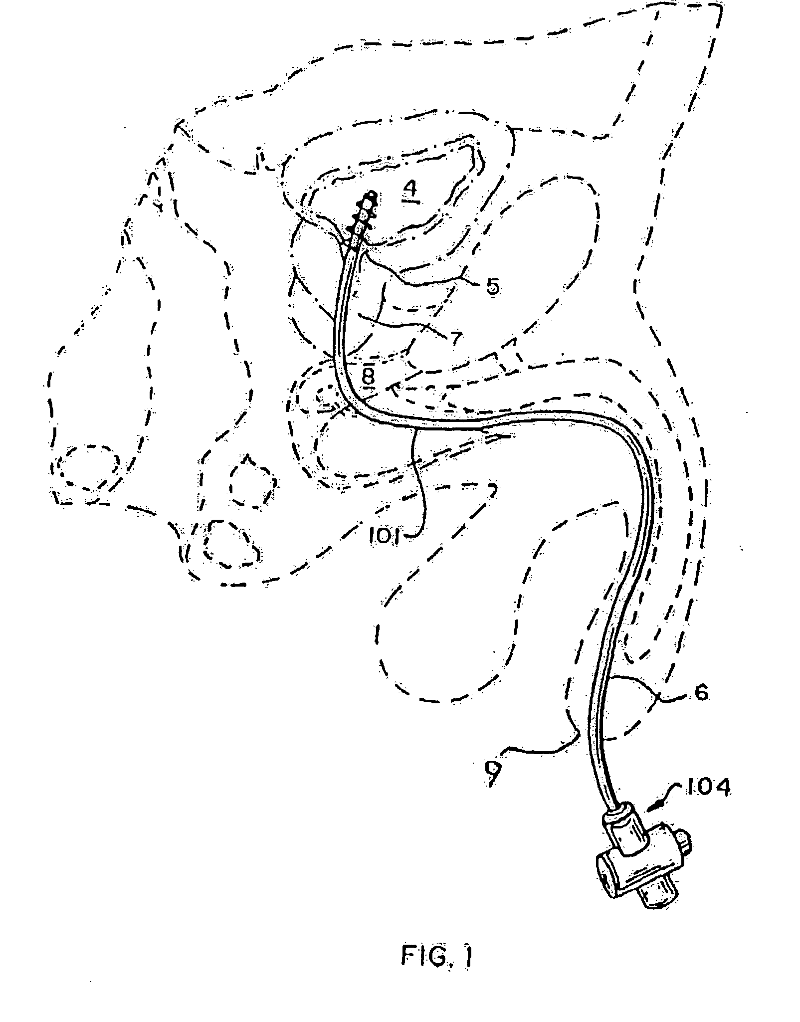
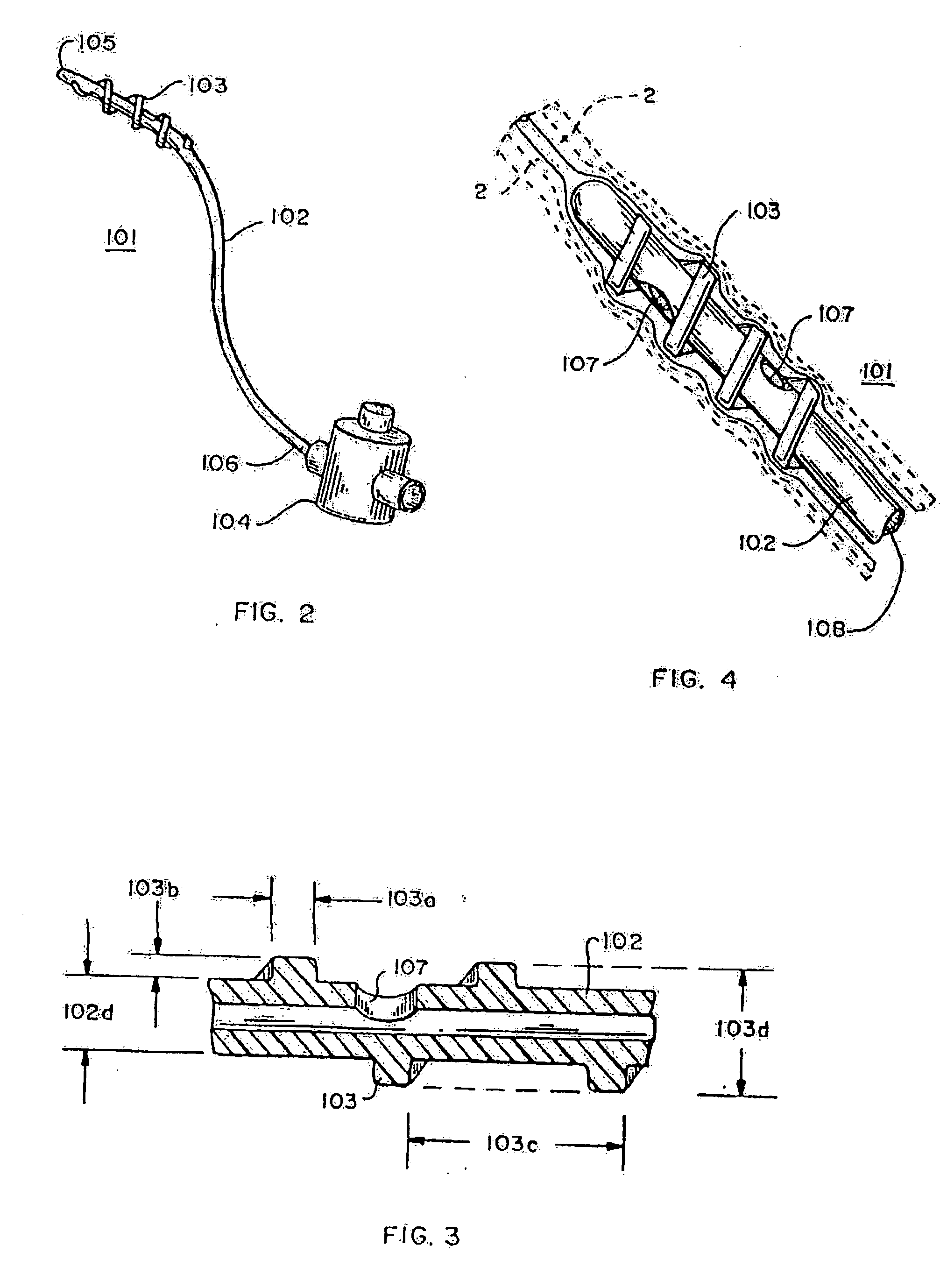
[0190] Referring now to FIGS. 1, 2 and 3, a threaded catheter 101 for males is made up of a tube 102 with an external thread 103, attachable to a flow control device 104. Tube 102 is extruded from a polyurethane material, has an inside diameter of 0.06 inches, an outside diameter 103d of 0.125 inches, and is...


PUM


Abstract

Apparatus for accessing a bodily passageway, the apparatus comprising: a flexible tube having a distal end and a proximal end, a longitudinal axis extending between the distal end and the proximal end, and a lumen extending from the distal end to the proximal end, the lumen being sized to receive matter to be transported through the bodily passageway; and an external thread disposed over the distal end of the tube, the external thread having a sufficient structural integrity, and a sufficient surface profile, such that when the tube is disposed in a bodily passageway, rotation of the tube about the longitudinal axis will result in longitudinal motion of the tube along said bodily passageway.

Description

REFERENCE TO PENDING PRIOR PATENT APPLICATIONS [0001] This patent application: [0002] (i) is a continuation-in-part of U.S. patent application Ser. No. 11 / 189,561, filed Jul. 26, 2005 by James J. Frassica for ROTATE TO ADVANCE CATHETERIZATION SYSTEM (Attorney's Docket No. FA-63 CIP CON 3); [0003] (ii) is a continuation-in-part of U.S. patent application Ser. No. 11 / 121,751, filed May 4, 2005 by James J. Frassica for ROTATE-TO-ADVANCE CATHETERIZATION SYSTEM (Attorney's Docket No. FA-70 CON); [0004] (iii) is a continuation-in-part of U.S. patent application Ser. No. 11 / 363,990, filed Feb. 28, 2006 by James J. Frassica et al. for ROTATE-TO-ADVANCE CATHETERIZATION SYSTEM (Attorney's Docket No. FA-71); and [0005] (iv) claims benefit of pending prior U.S. Provisional Patent Application Ser. No. 60 / 682,584, filed May 19, 2005 by James J. Frassica for ROTATE-TO-ADVANCE CATHETERIZATION SYSTEM (Attorney's Docket No. FA-72 PROV). [0006] The four above-identified patent applications are hereby ...

Claims


Application Information

Patent Timeline
IPC IPC(8): A61M27/00A61F2/94
CPCA61B1/042A61B1/015A61B1/307A61B19/5212A61B2017/00685A61B2017/349A61F2/0009A61F2/88A61F2/94A61M25/0017A61M25/0021A61M25/0026A61M25/0043A61M25/0052A61M25/0068A61M25/007A61M25/0075A61M25/01A61M25/0102A61M25/0105A61M25/0108A61M25/04A61M25/10A61M25/1002A61M27/008A61M2025/006A61M2025/0191A61M2025/1086A61B1/0008A61B1/00154A61B1/0016A61B1/273A61B90/361A61B1/00148
Inventor FRASSICA, JAMES J.AILINGER, ROBERT E.
Owner OLYMPUS ENDO TECH AMERICA
Why Eureka
Try Eureka