
Method for building powerful calculations of an entity relationship model

a relationship model and entity technology, applied in the field of entity relationship modeling, can solve the problems of difficult to construct powerful calculations, large complexity of relationships, and conventional tools for creating calculations using er models that do not scale well to a user's level of experience, and achieve the effect of easy to s

Inactive Publication Date: 2007-01-04
MICROSOFT TECH LICENSING LLC
View PDF7 Cites 14 Cited by
  • Summary
  • Abstract
  • Description
  • Claims
  • Application Information

AI Technical Summary

Benefits of technology

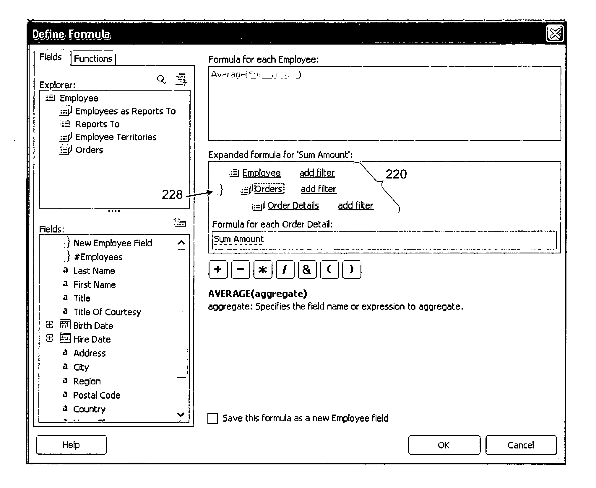
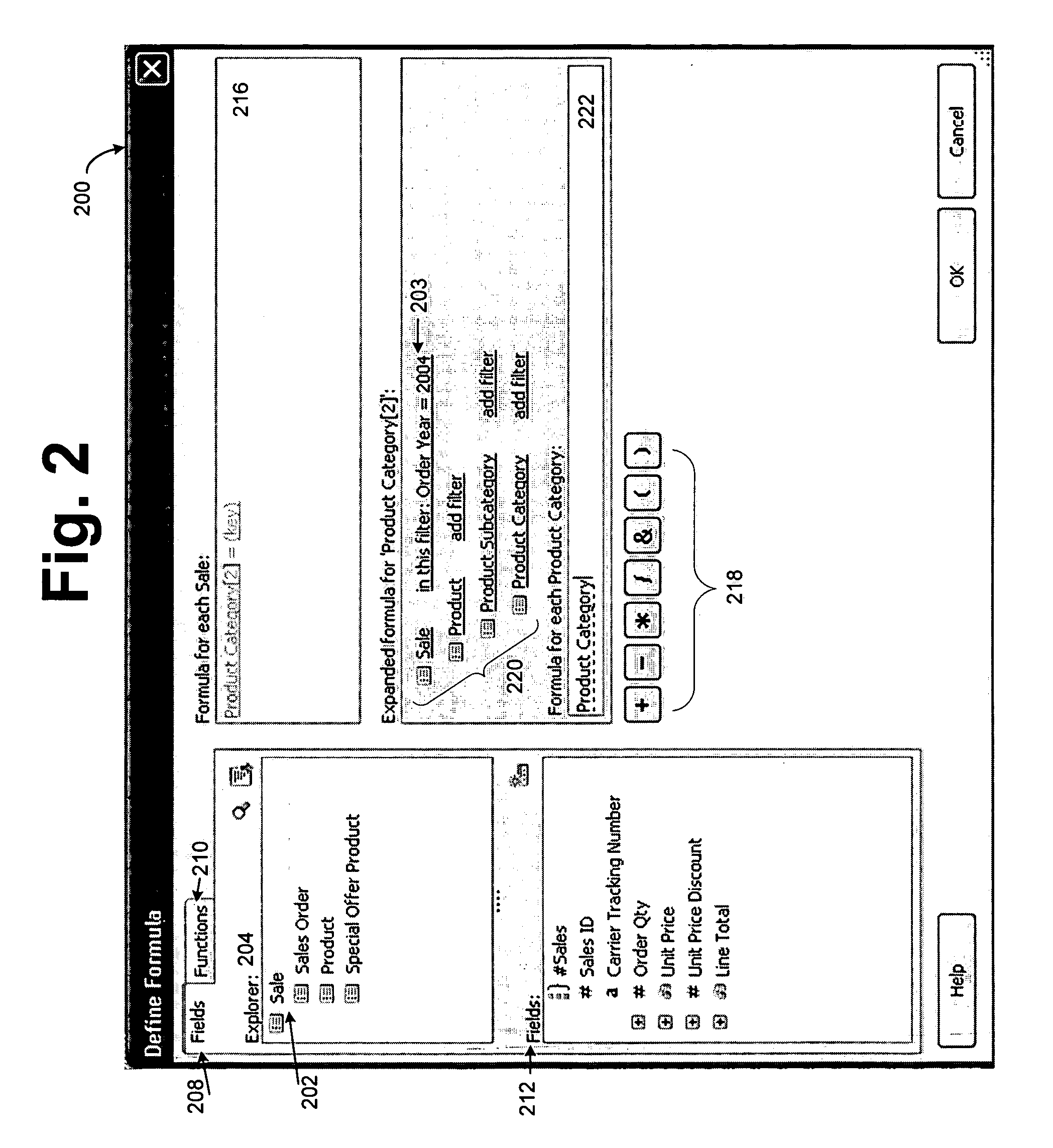
[0007] A method of creating and defining complex functions and / or expressions that may be run against an entity relationship model. A primary entity serves as a beginning point of the query and determines what data that will be returned by the user-created report. When a relationship from any entity is traversed, including the primary entity, the role name for the target entity is displayed hierarchically beneath the entity it was navigated from. A tree is formed from the primary entity to all other entities involved in the query which allows the user to easily see what entities and relationships are available to be used in the query. In addition, expressions may be anchored to any entity. When the expression is used in a report, the query changes according to the contents of the expression (either the field is anchored to the existing query or the base entity may change depending on the contents of the expression).
[0008] Also, when an entity is selected, the relationships from this entity are shown as possible navigation paths. The user may select one of these paths to navigate and add to the query tree or chose a field from the field list. It also allows the user to quickly return to any entity used in the query to add additional fields or traverse another relationship. If the user changes the primary entity during the building of a query, the navigation zone is reconstituted with the new primary entity at the root.

Problems solved by technology

Because of the nature and flexibility of ER models, it can be difficult to construct powerful calculations.
Much of the complexity comes from the relationships.
Conventional tools for creating calculations using ER models do not scale well to a user's level of experience.
However, these tools are either too simple or too difficult to use.

Method used


Image

  • Method for building powerful calculations of an entity relationship model
  • Method for building powerful calculations of an entity relationship model
  • Method for building powerful calculations of an entity relationship model

Examples


Embodiment Construction

[0014] Exemplary Computing Environment

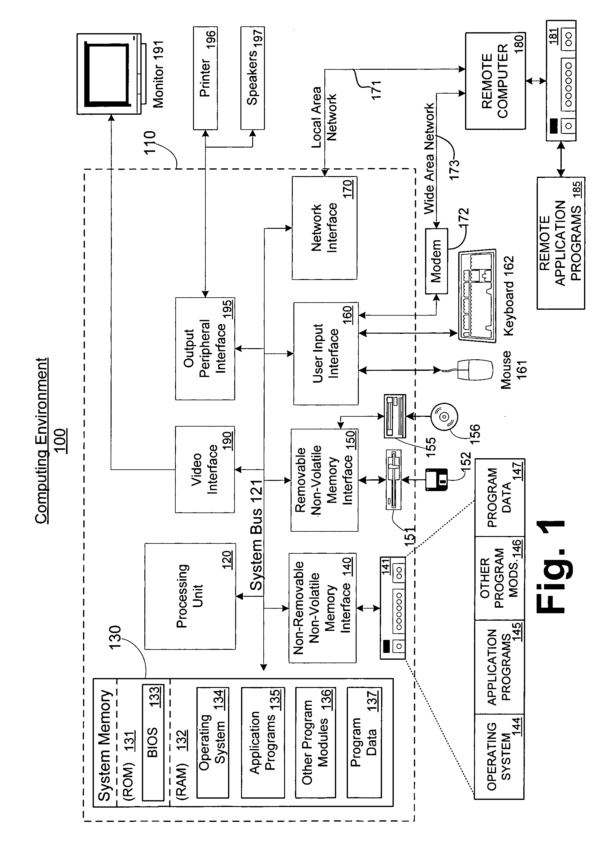
[0015]FIG. 1 illustrates an example of a suitable computing system environment 100 in which the invention may be implemented. The computing system environment 100 is only one example of a suitable computing environment and is not intended to suggest any limitation as to the scope of use or functionality of the invention. Neither should the computing environment 100 be interpreted as having any dependency or requirement relating to any one or combination of components illustrated in the exemplary operating environment 100.

[0016] The invention is operational with numerous other general purpose or special purpose computing system environments or configurations. Examples of well known computing systems, environments, and / or configurations that may be suitable for use with the invention include, but are not limited to, personal computers, server computers, hand-held or laptop devices, multiprocessor systems, microprocessor-based systems, set top bo...


PUM


Abstract

A method of creating and defining complex functions and / or expressions that may be run against an entity relationship model. An anchor entity serves as a beginning point of the expression and determines what data that will be returned by the user-created expression within the context of a query. When a relationship from any entity is traversed, including the anchor entity, the role name for the target entity is displayed hierarchically beneath the entity it was navigated from. When an entity is selected, the relationships from this entity are shown as possible navigation paths. The user may select one of these paths to navigate and add to the query tree or chose a field from the field list. Entities can be dragged and dropped into a formula area to create the expression. Functions, and mathematical and logical operations can be performed on the entities and fields in creating the expression. The fields and entities can be filtered to refine the results retrieved by the expression.

Description

FIELD OF THE INVENTION [0001] This invention relates in general to the field of entity relationship modeling. More particularly, this invention relates to a method of creating calculations that are performed on an entity relationship model. BACKGROUND OF THE INVENTION [0002] An entity relationship (ER) diagram is a graphical representation of an organization's data storage requirements. Entity relationship diagrams are abstractions of the real world which simplify a problem to be solved while retaining its essential features. Entity relationship diagrams have three different components: entities, attributes and relationships. Entities are the people, places, things, events and concepts of interest. Entities may represent collections of things, for example, an employee entity might represent a collection of all the employees that work for an organization. Individual members (employees) of the collection are called occurrences of the employee entity. [0003] Entities are further descri...

Claims


Application Information

Patent Timeline
IPC IPC(8): G06F17/30
CPCG06F17/30604G06F16/288
Inventor CHAU, CAROLYN KHANHCARLSON, JASON DAVIDMEYERS, ROBERT ALAN
Owner MICROSOFT TECH LICENSING LLC
Learn More