Testing apparatus and testing method

a testing apparatus and test method technology, applied in the field of testing apparatus and testing methods, can solve the problem of inability to accurately test the device under test including the high-speed serial interfa

Active Publication Date: 2007-01-04
ADVANTEST CORP
View PDF5 Cites 14 Cited by
  • Summary
  • Abstract
  • Description
  • Claims
  • Application Information

AI Technical Summary

Benefits of technology

[0007] Therefore, it is an object of the present invention to provide a testing apparatus, which is capable of overcoming the above drawbacks accompanying the conventional art. The above

Problems solved by technology

Thus, it is impossible to test a device under test i

Method used


Image

  • Testing apparatus and testing method
  • Testing apparatus and testing method
  • Testing apparatus and testing method

Examples


Embodiment Construction

[0031] The invention will now be described based on the preferred embodiments, which do not intend to limit the scope of the present invention, but exemplify the invention. All of the features and the combinations thereof described in the embodiment are not necessarily essential to the invention.

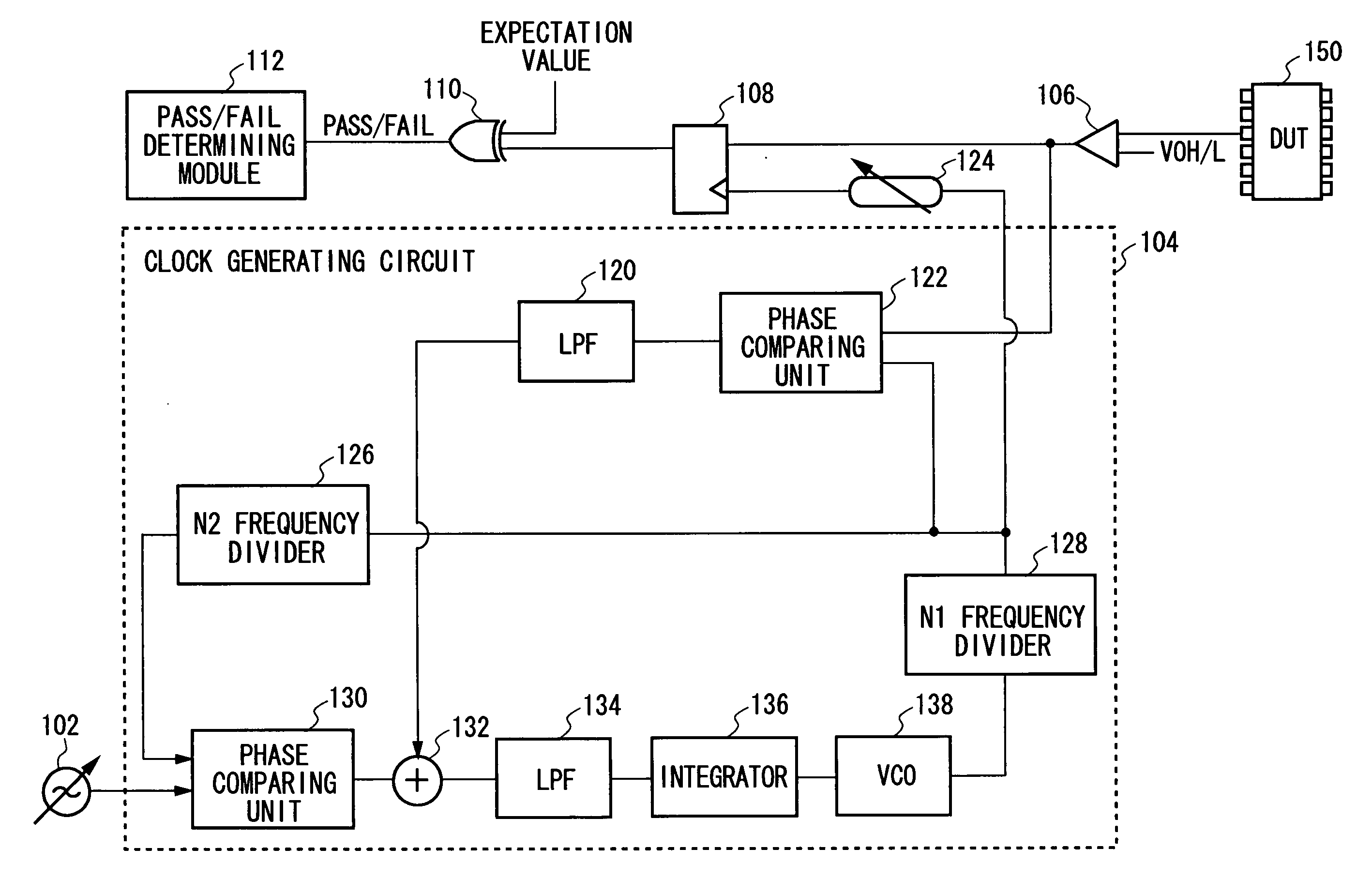
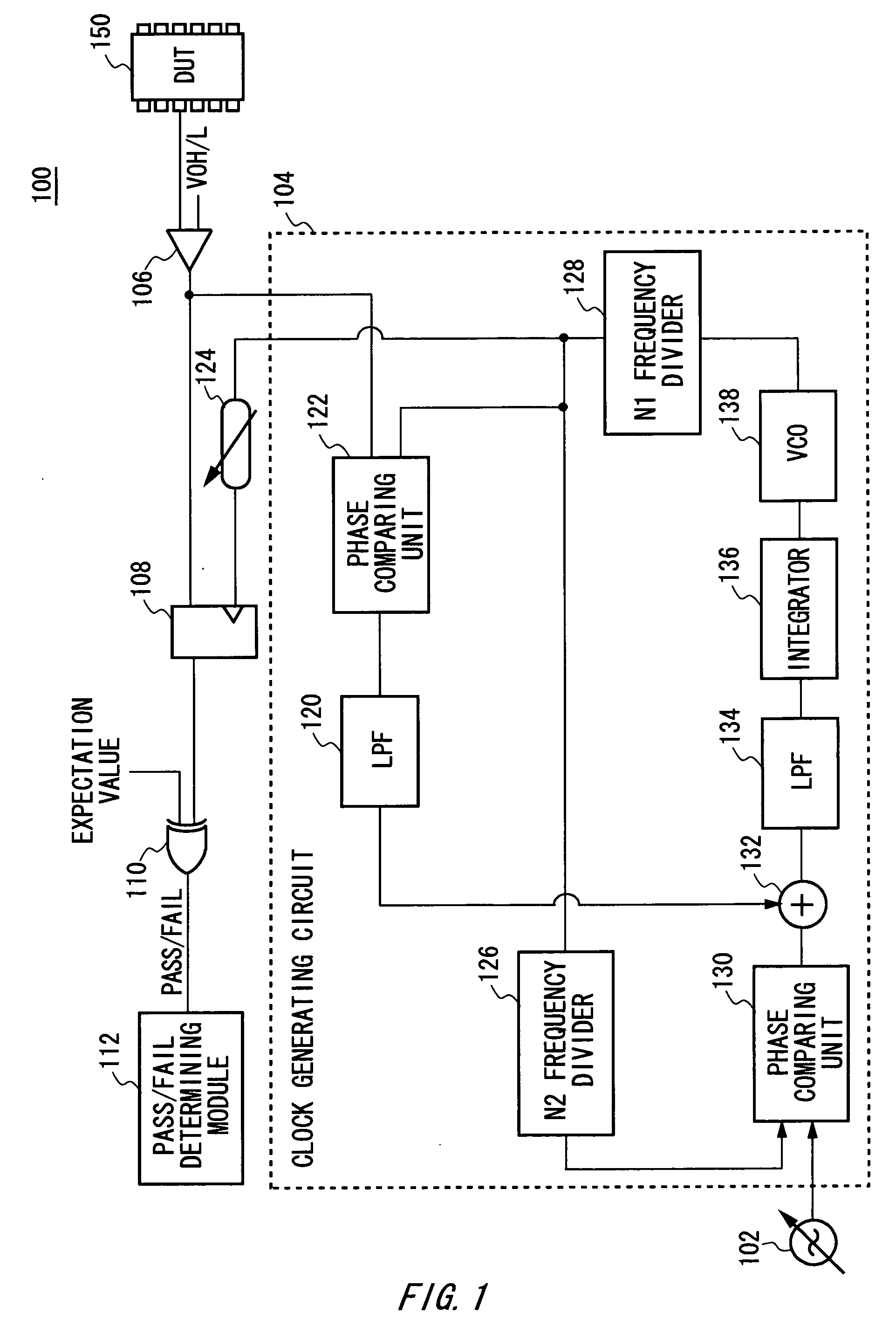
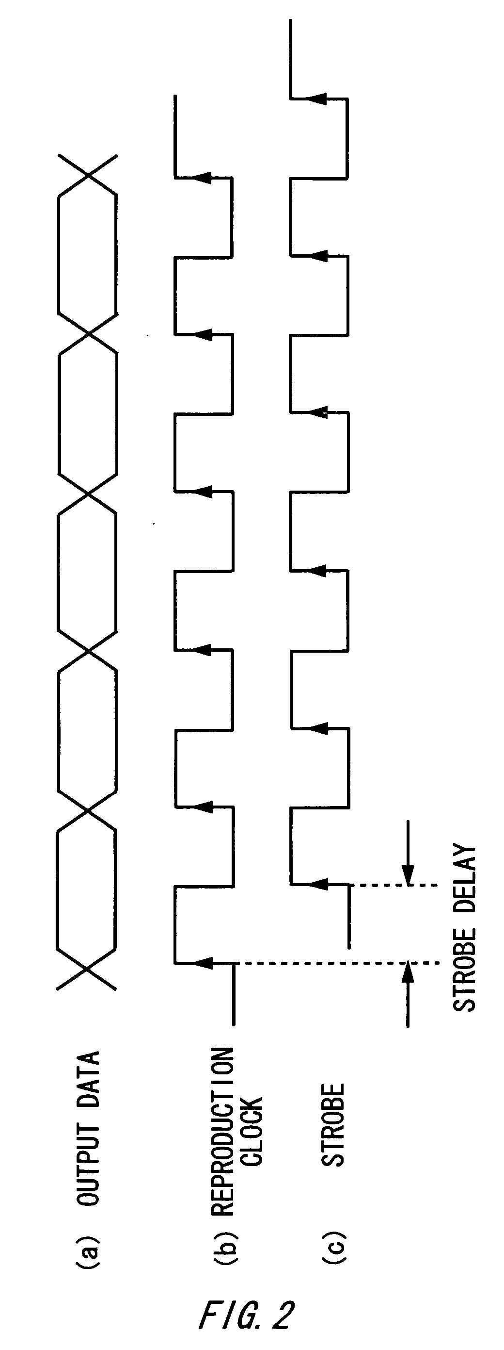
[0032]FIG. 1 shows an example of the configuration of a testing apparatus 100 according to a first embodiment of the present invention. FIG. 2A shows an example of a timing chart of output data of a DUT 150 according to the first embodiment. FIG. 2B shows an example of a timing chart of a reproduced clock generated by a VCO 138 according to the first embodiment. FIG. 2C shows an example of a timing chart of a strobe generated by a variable delay circuit 124 according to the first embodiment.

[0033] The testing apparatus 100 includes a reference clock source 102, a clock generating circuit 104, a level comparator 106, a variable delay circuit 124, a timing comparator 108, a logic comparing u...


PUM


Abstract

A testing apparatus according to the present invention includes: a clock generating circuit for generating a reproduced clock of which frequency and phase are substantially the same as frequency of the reference clock and phase of output data of a device under test, respectively; a delay circuit for generating a strobe for delaying the reproduced clock; a timing comparator for obtaining an output value of the output data based on the strobe; a logic comparing unit for comparing the output value with a predetermined expectation value; and a pass/fail determining module for determining pass/fail of the device under test based on the comparison result of the logic comparing unit, and the clock generating circuit includes: a first phase comparing unit for comparing phase of the output data of the device under test with that of the reproduced clock and outputting a first comparison result signal; a second phase comparing unit for comparing phase of the reference clock with that of the reproduced clock and outputting a second comparison result signal; and a reproduced clock generating module for generating the reproduced clock based on the first and second comparison result signals.

Description

[0001] The present application is a continuation application of PCT / JP2005 / 004370 filed on Mar. 11, 2005, claiming priority from a Japanese patent application No. 2004-93310 filed on Mar. 26, 2004, the contents of which are incorporated herein by reference.BACKGROUND OF THE INVENTION [0002] 1. Field of the Invention [0003] The present invention relates to a testing apparatus and a testing method. More particularly, the present invention relates to a testing apparatus and a testing method for testing a memory to be tested. [0004] 2. Description of the Related Art [0005]FIG. 6 shows the configuration of a conventional testing apparatus 600. The testing apparatus 600 includes a level comparator 604, a timing comparator 606, and a logic comparing unit 608. The level comparator 604 conducts voltage comparison of output data output from a device under test 602 (hereinafter, referred to “DUT”), and then, the output data is obtained by the timing comparator 606 by a strobe generated at a ti...

Claims


Application Information

Patent Timeline
IPC IPC(8): G06F11/00G01R31/28G01R31/3193G11C29/56G11C29/00
CPCG01R31/31932G01R31/2882G11C29/56012G11C2029/5602
Inventor KANTAKE, SHUSUKE
Owner ADVANTEST CORP
Why Eureka
Try Eureka